background image

20

The contents of this catalog are current as of date of 11/2013. Contents are subject to change without notice for the purpose of improvements.

FH12 Series

0.5mm and 1mm Pitch Connectors For FPC/FFC

Vertical Mounting type (common for 0.5 mm/1 mm pitch)
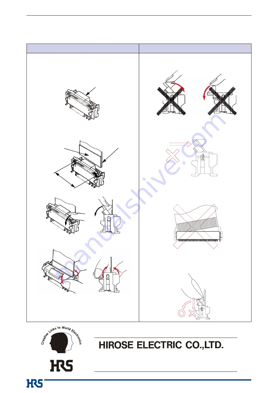
Operation

Precautions

1. FPC/FFC Termination procedure.

Connector installed on the board.

1) Verify that the actuator is positioned upright.

If the actuator has rotated to the side, care-
fully rotate it upright.

2) Insert the FPC/FFC vertically in the connector

slot assuring that the conductive traces of the
FPC/FFC are facing away from the actuator.

1) Avoid forcing the actuator up or down without

the FPC/FFC inserted.

3) Do not insert the FPC/FFC diagonally. Doing so

will result in the corners of the FPC/FFC catching
on the contacts and will cause deformation of the
contacts.

Actuator upright

FPC/FFC conductive traces

Stiffener

Slot

3) Press down the actuator in the direction shown.

2. FPC/FFC Removal

Rotate the actuator upward and withdraw the FPC/FFC.

2) Do not attempt to open or over rotate an already

released actuator (refer to the diagram below).
These actions may damage the actuator.

4) Do not press down vertically on the actuator when

the FPC/FFC already inserted, it needs to be rotat-
ed to engage the lock. Refer to the diagram below.

Doing so may cause actuator failure.

6-3,Nakagawa Chuoh-2-Chome,Tsuzuki-Ku,Yokohama-Shi 224-8540,JAPAN
TEL: +81-45-620-3526  Fax: +81-45-591-3726
http://www.hirose.com
http://www.hirose-connectors.com

®

Summary of Contents for FH12 Series

Page 1: ...he lock lever is open Doing so will cause the lock lever to become disen gaged or will damage the hook portion of the connector body 4 When inserting the FPC FFC do not forcefully rub against the surface beneath the connector insertion slot Doing so will result in the FPC FFC forcefully striking the contacts and this will cause contact deformation peeling of the FPC FFC conductors and other irregu...

Page 2: ...or able engagement of the lock lever in which the lock lever is raised To correct this first remove the FPC FFC and then reinsert it Forcing the lock will damage the connector 7 When locking handle the FPC FFC so that a load is not applied to the FPC FFC as would occur by pulling the FPC FFC or lifting it etc When a load is applied in the opposite direc tion to the rotational movement of the lock ...

Page 3: ...uctive traces Stiffener FPC insertion area 1 Avoid further lifting of the actuator once the lock has been released Doing so will cause the lock lever to separate from the rotational shaft and the lock lever will become disengaged or the hook portion of the connector body will be damaged 2 Avoid further pressing of the lock portion from the locked condition when the FPC FFC has not yet been inserte...

Page 4: ...ithout the FPC FFC inserted 3 Do not insert the FPC FFC diagonally Doing so will result in the corners of the FPC FFC catching on the contacts and will cause deformation of the contacts Actuator upright FPC FFC conductive traces Stiffener Slot 3 Press down the actuator in the direction shown 2 FPC FFC Removal Rotate the actuator upward and withdraw the FPC FFC 2 Do not attempt to open or over rota...

Reviews: