background image

2

DF13 Series

1.25mm Pitch Miniature Crimping Connector (UL Listed)

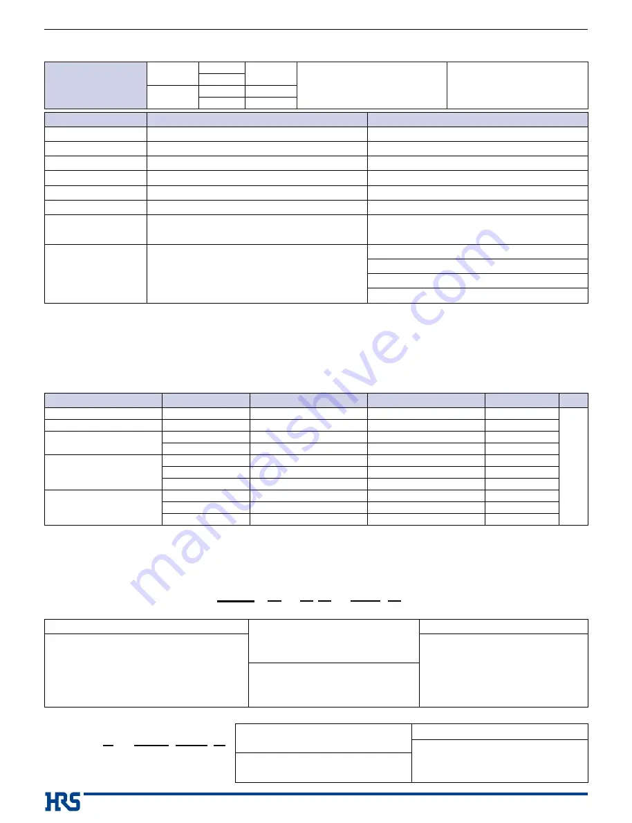
Product Specifications

Rating

Operating Temperature Range : 

-

35

to 

+85

ç (Note 1)

Storage Temperature Range : 

-

10

to 

+60

ç (Note 2)

Operating Moisture Range : 20

to 

80

% (Note 3)

Storage Moisture Range :  40

to 

70

% (Note 2)

Current rating

Specification

1A/pin

UL

Voltage rating

Specification

150V AC/DC

UL

29.9V AC/DC

Note 1 : Includes temperature rise caused by current flow.
Note 2 : The term "storage" refers to products stored for long period of time prior to mounting and use.

Operating Temperature Range and Humidity range covers non conducting condition of
installed connectors in storage, shipment or during transportation.

Note 3 : Use without condensation on parts.
Note 4 : Information contained in ths catalog represents general requirements for this Series. 

Contact us for the drawings and specifications for a specific part number shown.

UL File No. and Recognition
No. UL : E52653

Item

Specification

Condition

1.Insulation Resistance

500M

ø 

min.

100V DC

2.Withstanding voltage

No flashover or insulation breakdown.

500V AC/1 minute

3.Contact Resistance

30m

ø 

max.

100mA

4.Vibration

No electrical discontinuity of 1μs or more

Frequency : 10 to 55 Hz, single amplitude of 0.75 mm, 2 hours in each of the 3 directions.

5.

Humidity (Steady state)

Contact resistance : 30m

ø 

max. Insulation resistance : 500M

ø 

min.

96 hours at temperature of 40ç and humidity of 90% to 95%

6.Temperature Cycle

Contact resistance : 30m

ø 

max. Insulation resistance : 500M

ø 

min.

(-55

ç 

: 30 minutes

5

to 

35

ç 

: 10 minutes

85

ç 

: 30 minutes

5

to 

35

ç 

: 10 minutes) 5 cycles

7.Durability (Mating/un-mating) Contact resistance : 30m

ø 

max. 

Tin plating : 30 cycles

Gold plating : 50 cycles

8.Resistance to Soldering heat

No deformation of components affecting performance.

Flow : 250ç for 10 seconds 

Manual soldering : 300ç for 3 seconds

Reflow : At the recommended temperature profile

Manual soldering : 300ç for 3 seconds

Materials/Finish 

Product

Part

Material

Finish

Remarks

RoHS2

Crimping Socket

Insulator

Polyamide

Beige

UL94V-0

Crimping Contact for Socket

Contact

Phosphor copper

Tin plated or gold plated

-

-

-

-

Pin Header (Through hole)

Insulator

Polyamide

Beige

UL94V-0

Contact

Brass

Tin plated

-

-

-

-

Insulator

Polyamide

Beige

UL94V-0

Yes

Pin Header (SMT Single row)

Contact

Brass

Tin plated or gold plated

-

-

-

-

Metal Fitting

Phosphor copper

Tin plated

-

-

-

-

Insulator

Polyamide

Beige

UL94V-0

Pin Header (SMT Double row)

Contact

Brass

Tin plated or gold plated

-

-

-

-

Metal Fitting

Phosphor copper

Tin plated

-

-

-

-

Contact

DF13   #  -  2630  SCF  A

q

w

r

e

q

Style Symbol

Blank : Standard

G : Low insertion / extraction

w

Applicable Cable Size 2630 : 26

to 

30 AWG

3032 : 30

to 

32 AWG

e

Packaging Type  SCF : Socket Contact/Reel

r

Plating Type

Blank : Tin plated

A : Gold plated

DF13    

#

-  

*

S  -  1.25  C

q

e

w

r

t

y

e

Number of Contacts

r

Single row : 2

to 

12, 14, 15

r

Double row : 10, 20, 30, 40

r

Connector Type

t

S : Single row socket / P : Single row pin header

t

DS : Double row socket / DP : Double row pin header

t

Contact Pitch : 1.25mm

y

Connection Form / Contact Style.

C : Crimping socket / DSA : Straight through hole

DS : Right angle through hole / V : Straight SMT

H : Right angle SMT

q

Series Name

: DF13

w

Style Symbol

: Blank : With boss

A : Without boss

C : Without boss

Connector

Product Number Structure 

Refer to the chart below when determining the product specifications from the product number.
Please select from the product numbers listed in this catalog when placing orders.

(

Feb.1.2021 Copyright 2021 HIROSE ELECTRIC CO., LTD. All Rights Reserved.

Summary of Contents for SignalBee DF13 Series

Page 1: ...secures automatic mounting by the embossed tape packaging In addition the tube packaging can be selected Fig 1 4 Integral Basic Function Despite Miniature Size The header is designed in a scoop proof box structure and completely prevents mis insertion In addition the surface mounting SMT header is equipped with the metal fitting to prevent solder peeling Fig 1 5 UL Certifled Applications Note PC m...

Page 2: ...max Tin plating 30 cycles Gold plating 50 cycles 8 Resistance to Soldering heat No deformation of components affecting performance Flow 250ç for 10 seconds Manual soldering 300ç for 3 seconds Reflow At the recommended temperature profile Manual soldering 300ç for 3 seconds Materials Finish Product Part Material Finish Remarks RoHS2 Crimping Socket Insulator Polyamide Beige UL94V 0 Crimping Contact...

Page 3: ...7 90 9 15 10 40 11 65 No of Contacts A B Part No HRS No DF13 9S 1 25C DF13 10S 1 25C DF13 11S 1 25C DF13 12S 1 25C DF13 13S 1 25C DF13 14S 1 25C DF13 15S 1 25C 536 0008 3 536 0009 6 536 0010 5 536 0011 8 536 0012 0 536 0013 3 536 0014 6 9 10 11 12 13 14 15 10 00 11 25 12 50 13 75 15 00 16 25 17 50 12 90 14 15 15 40 16 65 17 90 19 15 20 40 No of Contacts A B Note The quantity is delivered per bag 1...

Page 4: ...Straight Pin Header Through hole Single Row Right Angle Pin Header Through hole Board Through hole Diameter Ø0 6 0 03 Specific No Blank Tin plated 75 Tin plated tube packaging 5 10 BTube Dimensions 115 89 72 61 52 46 41 TubePackagingQuantity 37 34 31 29 27 25 23 TubePackagingQuantity Note 1 The quantity at the specific No None is delivered per bag 100pcs If needed please select and order the produ...

Page 5: ...P 1 25V DF13C 6P 1 25V DF13C 7P 1 25V DF13C 8P 1 25V DF13C 9P 1 25V DF13C 10P 1 25V DF13C 11P 1 25V DF13C 12P 1 25V DF13C 14P 1 25V DF13C 15P 1 25V 536 0401 2 536 0402 5 536 0403 8 536 0404 0 536 0405 3 536 0406 6 536 0407 9 536 0408 1 536 0409 4 536 0410 3 536 0411 6 536 0413 1 536 0414 4 2 3 4 5 6 7 8 9 10 11 12 14 15 1 25 2 50 3 75 5 00 6 25 7 50 8 75 10 00 11 25 12 50 13 75 16 25 17 50 No of C...

Page 6: ...0301 8 536 0302 0 536 0303 3 536 0304 6 536 0305 9 536 0306 1 536 0307 4 536 0308 7 536 0309 0 536 0310 9 536 0311 1 536 0313 7 536 0314 0 2 3 4 5 6 7 8 9 10 11 12 14 15 1 25 2 50 3 75 5 00 6 25 7 50 8 75 10 00 11 25 12 50 13 75 16 25 17 50 No of Contacts A 4 15 5 40 6 65 7 90 9 15 10 40 11 65 12 90 14 15 15 40 16 65 19 15 20 40 B 7 15 8 40 9 65 10 90 12 15 13 40 14 65 15 90 17 15 18 40 19 65 22 1...

Page 7: ... 8 70 14 95 21 20 27 45 Spec No 21 Spec No 51 Emboss Width 24 32 44 44 Unit mm BPCB mounting pattern Note 1 Shaded area must be free of any electrically conductive traces to avoid contact with soldered pin header terminations Specific No 22 Tin plated embossed tape packaging 52 Gold plated embossed tape packaging Note 1 Please order the embossed tape packaging product according to reel number 1000...

Page 8: ...SCF Low insertion extraction DF13G 2630SCFA Low insertion extraction 536 0300 5 536 0299 8 536 0298 5 04 536 0641 6 536 0643 1 536 0642 9 UL 1061 1571 1061 1571 1061 1571 1061 1571 1061 1571 1061 1571 Tin plated Au plated Tin plated Au plated Wire size 26 AWG 28 AWG 30 AWG 30 AWG 32 AWG 26 AWG 28 AWG 30 AWG 30 AWG 32 AWG 26 AWG 28 AWG 30 AWG 26 AWG 28 AWG 30 AWG Strandedwireconductor 7Pieces φ0 16...

Page 9: ... Miniature Crimping Connector UL Listed Right Angle Straight SMT Double Row Product Through hole Single Row Product SMT Single Row Product BApplication Pattern Feb 1 2021 Copyright 2021 HIROSE ELECTRIC CO LTD All Rights Reserved ...

Page 10: ...4 0 4 0 1 0 38 4 0 1 2 0 1 13 0 1 1 75 0 1 C 0 1 B 0 1 A 0 3 5 1 A 0 3 B 0 1 C 0 1 1 75 0 1 4 0 1 2 0 15 A 44mm 12 0 1 0 3 0 1 4 1 0 15 1 1 Ø 1 5 0 1 0 Ø 2 1 0 8 Ø 5 2 5 0 1 0 BEmbossed Carrier Tape Dimensions KDF13C P 1 25V KDF13A P 1 25H KDF13EA DP 1 25V Product Type Size No of Contacts A B C D DF13C P 1 25V DF13A P 1 25H 2 3 4 to 10 11 to 14 15 16 24 32 44 28 4 40 4 7 5 11 5 14 2 20 2 16 4 24 4...

Page 11: ...aning is allowed Cleaning is not recommended because cleaning may change the mating withdrawal feeling etc Please contact us when you use other cleaning agents 6 Cautions Be careful for the excessive scoop insertion extraction which will cause damage to the product 7 Precautions Please refer to following documents in handling this product Crimp quality standards ETAD H0895 00 ETAD H0953 00 Wire to...

Page 12: ...nd press down continue pressing until there is a tactile click Method Grasp the cable so that the entire cable is pulled evenly and it out Caution Do not remove at an angle of 30 or greater Doing so will cause contact deformation or case damage Method Remove with the connector parallel Handing Angle of Removal The characteristics and the specifications contained herein are for reference purpose Pl...

Reviews: