HRW HPD0440BNMR V401 Manual 111116.doc E. & O. E. / Subject to change without notice Page 24 of 43
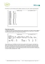
Enter P26 or any other starting point # to display another set of 21 device relevant sequential points.
Control Loop (CL)
To display the Control Loop statuses enter
C1
for loop 1,
C2
for loop 2, etc. Below we see the display of
CL2 (point 70) which shows the relevant input connections/statuses and output values, including the
connected physical outputs, for the supply air cooling control.
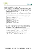
The control loop is set as DIR50 which means the loop output is 50% at set point. In this case the
DIR50 control reaction is used for driving a 3-point actuator, cooling application, with the associated
DO’s set for 10sec PWM cycle, DO1 (point 9) operating as open command when the loop output is
above 50% and DO2 (point 10) operating as the close command when the loop output is below 50%.
Point 37, a Digital Logic block 1, is set as the start signal for the control loop and as the enabling point
for the DO’s (DO sub-parameter #02 – AND).


