HRW HPD0440BNMR V401 Manual 111116.doc E. & O. E. / Subject to change without notice Page 37 of 43
Universal Inputs
UI 1 is fixed as NTC 10k internal sensor. UI 2 is fixed NTC 10k external sensor or Digital Input (DI). UI 3
is configured as external
10k NTC or DI by default
.
UI 4 is configured as external
0-10Vdc by default
.
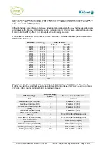
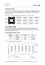
By reconfiguration of the UI resistor raft it is possible to use 10k…100k NTC, 0-10Vdc or 4…20mA
sensors at UI3 or UI4.
When making own raft configurations select ¼ Watt resistors of 1% tolerance or better.
Sensor Type
Input 3
Input 4
Resistance
10k NTC / DI
Link 1 to 8
Link 3 to 6
10k
Ω
100k NTC / DI
Link 1 to 8
Link 3 to 6
100k
Ω
0-10Vdc
Link 2 to 7
Link 4 to 5
100k
Ω
4…20mA
Link 1 to 2
Link 3 to 4
250
Ω
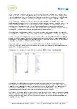
Linearisation Table
The Linearisation Table provides conversion of the UI physical signal in to an engineering value for
display and control in other areas of an application. Sensor Types 0…5 may be customised to suit
different scaling for a specific active sensor type or to suit a passive sensor element that is not already
pre-programmed as a factory default.
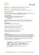
Factory Default Sensor Types
UI Sensor
Type
Sensor
Units Tag
Scale
0
100k NTC
Ctc
-10…90 °C
2
0-10Vdc
%V1
0…100%
3 4…20mA %mA 0…100%
5
10k NTC
Ctx
-10…90 °C
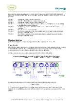
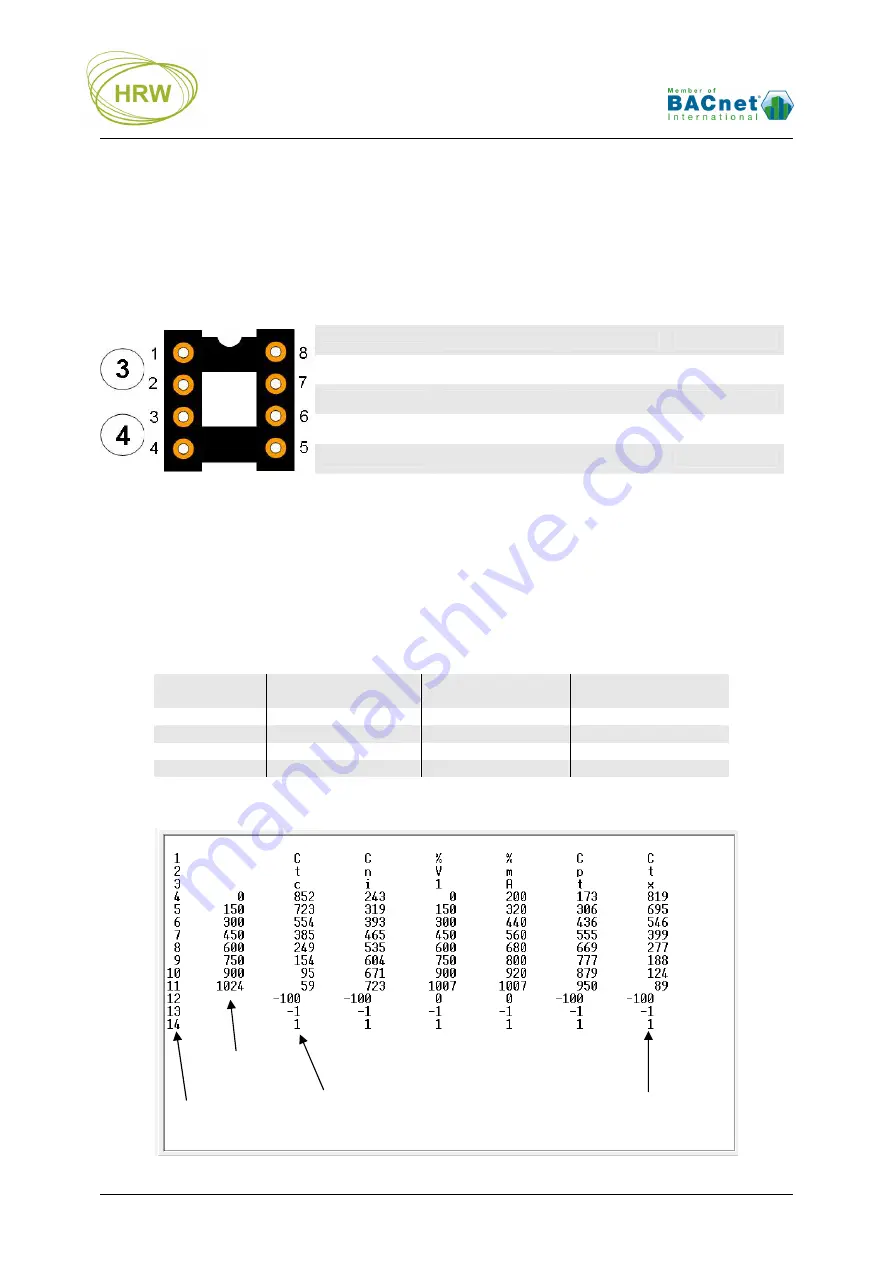
Enter <L> to display the default linearization table.
Row #
Column 2
(UI Sensor Type 0)
Column 7
(UI Sensor Type 5)
Column 1
(Reference)
Column 3
Column 4
Column 5
Column 6
Units character1
Units character2
Units character3
Intercept
Decimal shift (-2…2)
Multiplier (1…9)

