HRW HPD0440BNMR V401 Manual 111116.doc E. & O. E. / Subject to change without notice Page 40 of 43
Installation & Commissioning
This is an RS485 network device designed for mounting in an electrical panel. Ideally it should
be mounted to the panel backplane in a horizontal position (inputs on the lower side and
outputs on the upper side)
Each 24Vac power supply transformer should have the neutral (24Vac N) connection grounded
at the electrical panel earth connection to ensure the device grounding is at the same potential
as the network master’s grounding
Where more than one device is connected to a common transformer ensure that the 24Vac
phasing is the same to each device (‘A’ connects to ‘A’, ‘N’ connects to ‘N’ in all cases)
If the red comms light adjacent to the RS485 terminals emits an obvious flash every time 24Vac
power is applied to the device then the micro-processor may be corrupted. The micro processor
should be replaced
Twisted pair shielded cable must be used for the sensors and transmitters connected to the
universal inputs (UI’s). The sensor cable shield must be grounded, at the device end only
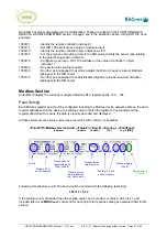
RS485 multi-drop cable should be used for the network connections, complete with end of line
terminating resistors (120
Ω
). Belden 9841 or equivalent is recommended. The recommended
cable is a low capacitance twisted pair with braid and foil screen
The RS485 cables should be terminated directly at each device in a daisy-chain configuration,
avoiding ‘laterals’ or ‘spurs’
The RS485 screen should be connected at the network master’s ground terminal. The incoming
and outgoing screen at each device should be continuously connected via the S terminal of the
device (note that the device’s S terminal has no electrical connection to the device, it merely
acts as a junction terminal for the purpose of screen continuity)
The RS485 cable should avoid cable routes that run with power cables. Where the RS485
cable must cross power cables then they should cross at 90° avoiding parallel runs beside
power cables
Prior to connection of the slave devices to the RS485 network check that no AC voltage is
present. Double check the network for short circuits between the twisted pair cores and
between the cores and the screen. Ensure continuity of the twisted pair cores and the screen
Check the network master’s +/- terminals for correct voltages to ground (approx. 2.5Vdc) and
connect the RS485 network cable to the network master’s RS485 port
At each device assign an individual address and the baud rate specific to the network. Write the
changes, eXit the terminal application and remove the HPECOM cable
Verify network voltage at the RS485 connector (b/- and ground) and connect to the
device. Communication can be verified by flashing of the red comms LED adjacent the 3
terminal RS485 connector). Frequency of comms LED flash is baud rate dependant. At higher
baud rates the LED flash may not be obvious, the LED appearing to be continuously on
Where a network runs between buildings and zero earth potential difference between individual
panel 24Vac power supplies cannot be guaranteed, we recommend that a repeater be used to
provide isolation of the sections of the network having differing earth potential

