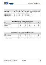
Installation and adjustment
FM 240 MuW Beta Type S Rev.01
2021-07-07
19
distributed by
6.4
Mounting a drive unit
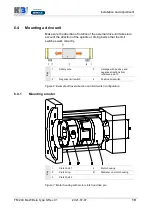
Make sure the direction of rotation of the external drive unit takes into
account the direction of the spindle or timing belt so that the limit
switches work correctly.
Ke
y
1
Safety zone
3
Carriage with positive and
negative directions from
reference point 0
2
Negative limit switch
4
Positive limit switch
Figure 6: Example of travel direction and limit switch configuration
6.4.1
Mounting a motor
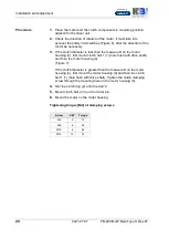
Ke
y
1
Clutch half 1
4
Motor housing
2
Clutch ring
D
Diameter on motor housing
3
Clutch half 2
Figure 7: Motor housing with motor clutch on drive pin
Summary of Contents for Beta 40-SGS
Page 2: ......

