background image

Maintenance 


26


2021-07-07 

FM 240 MuW Beta Type S Rev.01 


distributed by 

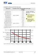
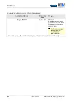
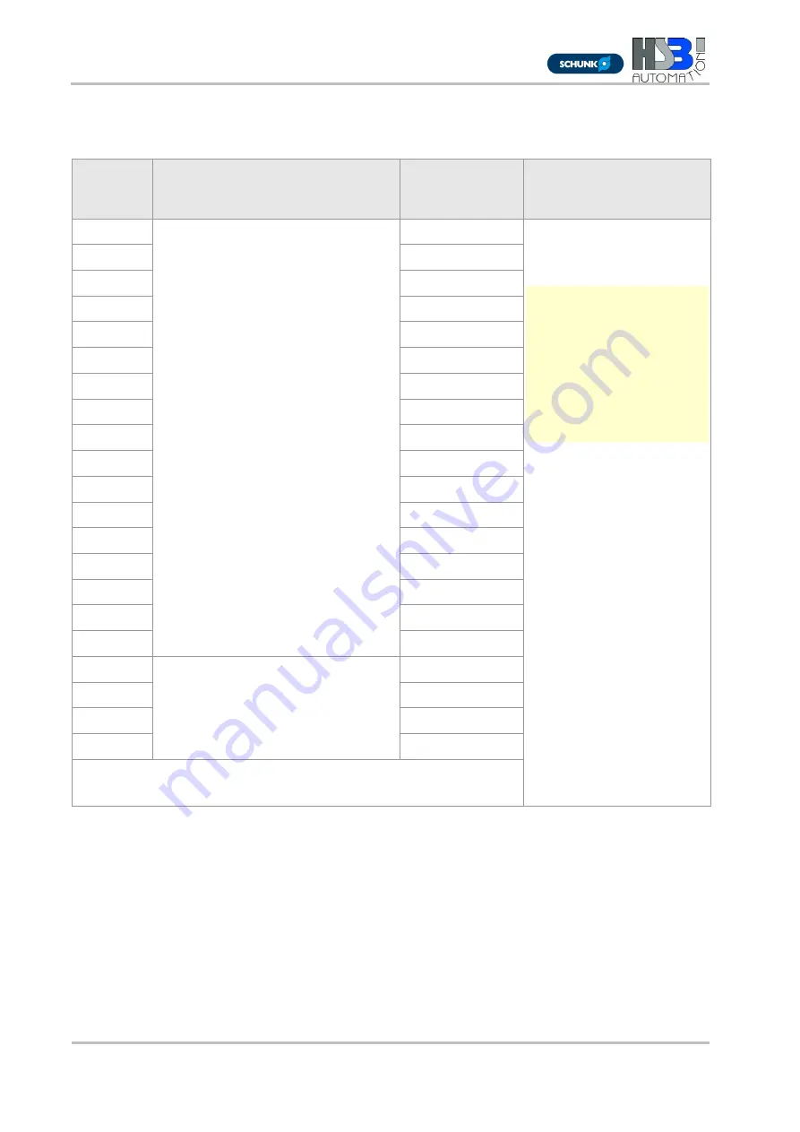
Schedule for lubrication point S (for ball screw drive)


BSD* type 

Lubrication intervals at 

roll-overs 

Grease quantity 

[cm³] per ball 

screw nut 

Grease type 

1204 

25.000.000** 

0,50 

Greases to DIN 51825-
KP2N-20, e.g. Klüberplex 
BE 31-102 


If other greases are 
used, pay attention to 
manufacturers’ 
specifications! 


Greases containing 
solid lubricant (e.g. 
graphite, MoS2) must 
not be used! 

1205 

0,55 

1605 

1,70 

1610 

1,80 

1620 

1,90 

2005 

2,00 

2020 

2,30 

2050 

4,50 

2505 

2,60 

2510 

3,40 

2525 

3,10 

2550 

4,80 

3205 

4,20 

3210 

13,10 

3220 

8,40 

3232 

5,30 

3240 

3,00 

4005 

15.000.000** 

5,30 

4010 

15,40 

4020 

10,20 

4040 

9,50 

*BSD = Ball Screw Drive 
** Or at least 2x per year. The lubrication interval depends on the ambient 
temperatures and on the loading (see figure 9

). Relubrication “in motion“! 


Summary of Contents for Beta 40-SGS

Page 1: ...14498 10 Info HSB Automation de www HSB Automation de Distributor SCHUNK GmbH Co KG Spann und Greiftechnik Bahnhofstr 106 134 74348 Lauffen Neckar Deutschland Tel 49 7133 103 0 Fax 49 7133 103 2399 info de schunk com www schunk com distributed by Original Assembly and Maintenance Manual Linear Unit Types Beta 40 SGS SSS Beta 50 C SRS ...

Page 2: ......

Page 3: ...y 6 3 Technical data Standard model 7 4 Product description 10 5 Transportation and storage 12 6 Installation and adjustment 13 6 1 Installing the linear unit by mounting rails 13 6 2 Screwing the linear unit into place from below 14 6 3 Setting maximum travel 15 6 3 1 Setting the positions of the inductive limit switches 15 6 3 2 Setting the positions of the mechanical limit switches 17 6 4 Mount...

Page 4: ...t in death or serious injury Indicates minor risk Failure to observe this notice may result in light to moderate injury or damage to property Note Indicates tips on use of the machine and optimising its efficiency 1 2 Regulation use The mechanical linear unit is intended for installation in machines and is used solely for manipulating positioning transporting palletising loading unloading clamping...

Page 5: ... negative pressure of 0 2 bar The linear unit must be relubricated with a grease suitable for use in clean rooms basic lubrication carried out using Klübersynth BEM 32 34 1 5 Use in explosive environments If the linear units are used in potentially explosive environments operators must take steps to prevent explosions in accordance with ATEX Directive 2014 34 EU and ensure explosion proofing is in...

Page 6: ...monised European standards or corresponding national standards Machinery Directive 2006 42 EC DIN EN ISO 12 100 2011 03 Safety of Machinery General Design Guidelines Risk Assessment and Reduction DIN EN ISO 13850 2008 09 Safety of machinery emergency stop devices DIN EN 60 204 1 2006 Electrical equipment for industrial machines 2004 108 EC EMC Directive EMVG German law relating to the electromagne...

Page 7: ...rive 1 9 Obligations of the operating company Instruction of personnel In accordance with EU Health and Safety Directive 89 655 EEC articles 6 1 and 7 and with the Framework Directive 89 391 EEC articles 1 1 and 6 1 the company operating the linear unit must provide personnel assigned to install operate maintain repair or dismantle the unit with appropriate instruction in particular with regard to...

Page 8: ...nty cover will be voided if the unit is not operated in accordance with the stipulated regulation use the instructions set out in this operating manual are not followed the unit is modified without the consent of the manufacturers screws sealed by locking varnish are unlocked The manufacturer s warranty in respect of maintenance and repair work applies only if original replacement parts are used ...

Page 9: ... 30 0 40 0 30 Maximum travel standard mm 890 890 860 Repeat accuracy mm 0 03 0 03 0 03 Operating temperature C continuous operation 0 80 0 80 0 80 Geometrical moment of inertia IY mm4 88914 235424 Geometrical moment of inertia IZ mm4 133632 294804 Length of standard carriage mm 120 150 Length of long carriage mm 200 200 Weight without travel kg 1 50 1 70 1 50 Weight per 100 mm travel kg 0 30 0 40 ...

Page 10: ... or forces the individual values must be reduced In case of doubt consult Technical Support Dynamic load ratings of ball screw drives Beta linear unit Model and size Nominal Ø in mm Pitch in mm Cdyn N Beta 40 Beta 50 C 12 4 3400 5 4400 40 14900 Dynamic load rating of ball screw nut to DIN 69051 1989 Dynamic load ratings of rail guides Beta linear unit Model Size Number of rails Number of carriages...

Page 11: ... 8 8 2 7 5 4 9 0 22 0 43 0 74 0 DIN912 ISO4762 10 9 3 0 5 7 9 0 22 0 43 0 74 0 DIN912 ISO4762 12 9 3 0 5 7 9 0 22 0 43 0 74 0 Tightening torques Nm for clutch with clamping hub Size 14 19 24 28 38 Clutch diameter mm 30 40 55 65 80 Screw size M3 M6 M6 M8 M8 Tightening torque Nm 1 34 10 50 10 50 25 00 25 00 Tightening torques Nm for clutch with clamping ring hub Size 14 19 24 28 38 Clutch diameter m...

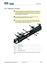
Page 12: ...ear unit with spindle drive Key 1 Fixed bearing 6 Lubricating nipple 2 Carriage 7 Thread drive 3 Cover band 8 Roller bearing guidance system 4 Movable bearing 9 Recirculating ball bearing 5 Base profile 10 Guide rail Figure 1 Component assemblies of the Beta 40 and Beta 50 C linear unit with spindle drive ...

Page 13: ...d moments in all directions and is positively connected to the guidance and drive elements by way of the so called drivers The base profile is self supporting up to a certain length and is equipped with grooves for mounting As an option the linear unit can be equipped with accessories such as a cover screw supports inductive or mechanical limit switches and other fittings see section 6 3 The effec...

Page 14: ... in impairment of its functions Risk of damage by heavy jolting or bending Transport the assembled linear unit only with the transit protection fitted To prevent damage during transportation and storage protect the linear unit against shaking and sliding as follows Stow it in a box of sufficient size Use packing Section 3 lists the unit weights Protect the unit against dirt corrosion water and agg...

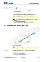
Page 15: ...n a flat surface Unit parallelism 0 2 mm 1 000 mm Mounting by the rails with tapped holes in them is the preferable solution for highly dynamic applications where the linear unit has only two attachment points 6 1 Installing the linear unit by mounting rails Figure 2 Mounting rails 1 The recommended maximum spacing between the mounting rails is 700 mm Procedure 1 Attach the mounting rails 1 loosel...

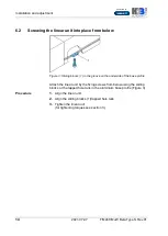
Page 16: ...ding blocks 1 in the groove on the underside of the base profile Attach the linear unit by the fixing screws from below using the sliding blocks or the tapped hole rails in the aluminium base profile Figure 3 Procedure 1 Align the linear unit 2 Align the sliding blocks 1 tapped hole rails 3 Tighten the linear unit for tightening torques see section 3 ...

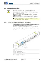
Page 17: ...ay only be connected by qualified electricians To stop the carriage promptly in the event of an emergency stop allow for adequate braking distance 6 3 1 Setting the positions of the inductive limit switches The function of inductive proximity switches is to shut down the electric drive before the mechanical end position is reached The necessary braking distance Δ B depends on the velocity and dece...

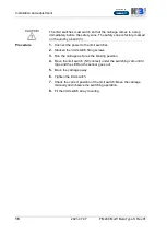
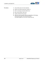
Page 18: ...ocedure 1 Connect the power to the limit switches 2 Slacken the limit switch fixing screws 3 Run the carriage as far as the braking position 4 Move the limit switch NC contact under the switching cam until it trips and the LED on the sensor goes out 5 Move the carriage away 6 Tighten the limit switch 7 Check the correct position of the limit switch Move the carriage manually and observe the switch...

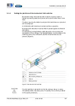
Page 19: ...switches is possible External shock absorbers must be fitted to protect against mechanical destruction The necessary braking distance Δ B depends on the velocity and deceleration of the carriage The braking distance must be between the switching point of the limit switch and the actual mechanical end position Figure 5 Key 1 Mechanical limit switches 2 Switching cam 3 Band marking safety zone 4 Bra...

Page 20: ...tches 2 Slacken the bracket fixing screw Figure 5 3 Run the carriage as far as the safety zone 4 Move the limit switch until it trips 5 Tighten the bracket fixing screw 6 Check the correct position of the limit switch Move the carriage manually and observe the switching operation If the braking distance is too short repeat the set up ...

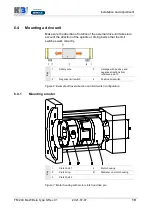
Page 21: ...iming belt so that the limit switches work correctly Key 1 Safety zone 3 Carriage with positive and negative directions from reference point 0 2 Negative limit switch 4 Positive limit switch Figure 6 Example of travel direction and limit switch configuration 6 4 1 Mounting a motor Key 1 Clutch half 1 4 Motor housing 2 Clutch ring D Diameter on motor housing 3 Clutch half 2 Figure 7 Motor housing w...

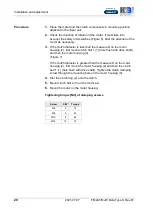
Page 22: ... measure D on the motor housing 4 first mount clutch half 1 1 hole flush with drive shaft and then the motor housing 4 Figure 7 If the clutch diameter is greater than the measure D on the motor housing 4 first mount the motor housing 4 and then the clutch half 1 1 hole flush with drive shaft Tighten the clutch clamping screw through the mounting hole on the motor housing 4 4 Slot the clutch ring 2...

Page 23: ...tallation Use of the deflection belt drive without the protective hood supplied is not permitted Only qualified electricians may carry out the electrical installation and check the direction of rotation Checks before start up Before starting the unit check the following Make sure the retaining fixtures conform to the mass and acceleration data provided by the manufacturers Make sure the machine or...

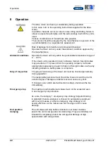
Page 24: ... operating company must take appropriate measures to prevent intrusion of foreign bodies such as by installing deflectors baffle plates or air barriers Duty of inspection The proper functioning of the linear unit must be checked periodically during operation The responsible personnel must check the linear unit and the line for external signs of damage and defects at least once every shift If chang...

Page 25: ...of personal injury or damage to other system components caused by falling system components Only authorised specialist personnel may disassemble the linear unit 1 Cut the power to the machine line 2 Dismantle the drive from the linear unit 3 Detach the linear unit from the machine line ...

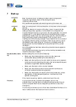
Page 26: ...components of the linear unit on a regular basis Relubricate the thread drives of the linear axes on a regular basis 10 1 Lubrication Influencing factors The following factors are key to determining the exact lubrication intervals required Loading Velocity Motion Operating temperature Degree of dirtying Short lubrication intervals Short lubrication intervals are necessary where there is susceptibi...

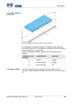
Page 27: ...ear unit The categories of lubrication point are identified by the markings S F O on the unit There is a separate lubrication schedule for each lubrication point category Lubrication point category Lubrication for Lubricant S Spindle Grease F Guide elements Grease O Guide elements Oil Lubrication method Lubrication should as far as possible take place while the unit is running so that the grease i...

Page 28: ...reases are used pay attention to manufacturers specifications Greases containing solid lubricant e g graphite MoS2 must not be used 1205 0 55 1605 1 70 1610 1 80 1620 1 90 2005 2 00 2020 2 30 2050 4 50 2505 2 60 2510 3 40 2525 3 10 2550 4 80 3205 4 20 3210 13 10 3220 8 40 3232 5 30 3240 3 00 4005 15 000 000 5 30 4010 15 40 4020 10 20 4040 9 50 BSD Ball Screw Drive Or at least 2x per year The lubri...

Page 29: ...h ball chain ca 1 5 35 with ball chain ca 1 7 12 with ball chain ca 0 14 12 without ball chain ca 0 15 15 without ball chain approx 2 000 km ca 0 8 20 without ball chain ca 1 4 25 L without ball chain ca 2 8 30 without ball chain ca 4 4 35 without ball chain ca 4 4 Or at least 2 x per year The lubrication interval depends on the ambient temperatures and on the loading see figure 9 Relubrication in...

Page 30: ...ion interval Oil quantity cm Oil type Every 2 000 km approx 0 4 Chainoil e g Klüberoil CM 1 220 or similar oil on the basis of mineral oil according ISO VG 220 If other oils are used pay attention to manufacturers specifications Or at least 2 x per year The lubrication interval depends on the ambient temperatures and on the loading ...

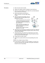
Page 31: ...ar unit components during installation and assembly Do not damage the standard parts screws pins etc or the dismantled components they will be refitted If cover bands are worn also replace the band guide elements If cover bands are damaged check the band guide elements for wear and replace them only as necessary Key 1 Clamp fittings 2 Stripper brushes 3 Driver 4 Cover band 5 Band hold down device ...

Page 32: ...d If the cover band is damaged only replace the band guide elements if they are damaged Fit press rollers a with the larger diameter on the outer 6 Push the new cover band with its broader side with the chamfered cutting edge facing downwards through the driver and fix it at one end by the clamp fitting 7 Carefully press the cover band into its guideway along its entire length until it audibly sna...

Reviews: