HSD
5801H0056
______________________________________________________________
167/181
8.8.15
Adjusting sensor S2 in HSK versions
B1 B2
HSK E25
6.5
6.35
HSK E40/F50 8.5
8.35
HSK E50/F63 10.5
10.3
HSK E63/F80 10.5
10.3
A
B
(+/- 0.1mm)
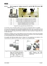
Figure 8 14. position of the
expeller
Figure 8 15. (A) expeller
(B) reference position
Table 8.1: values of (B)
After replacing the sensor as described in paragraph 8.8.12, calibrate it as follows:
1.
bring the spindle to the state of “Collet open (tool-holder cone expelled)” by powering the
cylinder; in these conditions, the position (B) (figure Figure
8 14.
) takes on the maximum
value;
2.
as shown in figures Figure
8 14.
and Figure
8 15.
, use a depth gauge to check that the
position (B) of the expeller in relation to the spindle nose takes on the value “B1” indicated in
table Table 8.1; if this is not the case, stop and contact HSD Customer Service;
3.
by means of the cylinder, bring the piston to the upper end stop and make position (B) adopt
the minimum value;
4.
power the cylinder by means of a one-way pressure regulator initially set at 0 bar;
5.
gradually increase the feed pressure so as to move the piston slowly forward, stopping when
the position (B) reaches the value “B2”;
6.
rotate sensor S2 until you find the position supplying the signal
“ON”
with (B) > B2 and
“OFF”
with (B) < B2;
7.
definitively tighten the screw (3);
8.
perform a cycle of 10 tool changes;
9.
at the end of the cycle, check that point [6] is satisfied without the need to rotate the sensor;
10.
if it is necessary to rotate the sensor, then repeat the whole procedure from the beginning;
11.
if it is not necessary to rotate the sensor, perform a cycle of 100 tool changes with the
machine, using the maximum possible number of different tool-holders;
12.
at the end of the cycle, check that point [6] is satisfied without the need to rotate the sensor;
13.
if it is necessary to rotate the sensor, then repeat the whole procedure from the beginning;
14.
if it is not necessary to rotate the sensor, then the S2 adjustment procedure is complete.
8.8.16
Adjusting sensor S3 (both ISO and HSK versions)
After replacing the sensor as described in paragraph 8.8.12, calibrate it as follows:
1.
check that the signal from the sensor corresponds to that described in the figure below
;
+ 24 V
0 V
0
giri
rev
1
2.
if this is not the case, rotate the bush (4) until you find the position that permits you to have the
output described in the above-mentioned table, then definitively tighten the screw (6).


