background image

HSD


5801H0056

_______________________________________________________________

23/181 

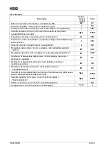
SP110.70.42_Air 

Description 

Unit of  

measur

ement 

Value 

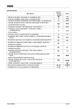
Potenza nominale / rated power / nennleistung (S1) 

kW 

Corrente nominale / rated current / nennstrom (S1) 

10.5 

Tensione nominale concatenata / line rated voltage / nennspannung 

380 

Velocità nominale al carico nominale/ rated speed at rated load / 
nenndrehzahl bei nennlast 

Rpm 

11850 

Frequenza nominale / rated frequency / nennfrequenz 

Hz 

400 

Tensione a vuoto concatenata / no-load line voltage / 

leerlaufspannung 

bei nennflussu 

370 

Corrente a vuoto / no-load current / leerlaufstrom 

4.3 

Resistenza dello statore / stator resistance / standerwiderstand kalt 

(20°C) 


0.27 

Resistenza del rotore /rotor resistance / lauferwiderstand kalt (20°C) 


0.24 

Reattanza di dispersione dello statore / stator leakage reactance / 
standerstreureaktanz 


1.6 

Reattanza di dispersione del rotore /rotor leakage reactance / 
lauferstreureaktanz 


3.2 

Reattanza del campo principale / main field reactance / 

hauptfeldreaktanz 


50 

Velocità di inizio indebolimento del campo / field weakening initial 

speed 

speed / Einsatzdrehzahl feldschwachung 

Rpm 

12000 

Velocità massima del motore / motor maximum speed / 

Maximaldrehzahl 

Rpm 

24000 

Fattore di potenza / power factor / nennleistungsfactor 


0.85 

Momento di inerzia del rotore / moment of inertia 

Kg m2 

1.1E-03 

Collegamento / circuit connection / schaltungsart 

Y or D 


Summary of Contents for ES915

Page 1: ...uctions for use HSD M E C H A T R O N I C D I V I S I O N 5801H0056 EN Rev 02 5801H0056 Rev 02__________________________________________________________ 1 181 ES884 ES888 ES915 ES919 ES929 ES939 ES983 ES988 ...

Page 2: ... Fixing specifications added Pressurisation values added Electrical connections of encoder models and with military connectors added Note on possible tie rod breakage added Sensor connections and positions updated Sensor adjustment procedure for HSK E63 models added List of spare parts and note on shaft kit updated This manual has been drawn up by the Electrospindles Technical Office of HSD S p A ...

Page 3: ...CARDS ES939 44 2 12 TECHNICAL CARDS ES983 52 3 TRANSPORT PACKAGING UNPACKING STORAGE 65 3 1 WARNINGS 65 3 2 DIMENSIONS AND WEIGHTS 65 3 3 TRANSPORT AND PACKAGING CONDITIONS 65 3 4 UNPACKING PROCEDURE 65 3 5 STORAGE 66 4 INSTALLATION AND INITIAL START UP 67 4 1 CHECK 67 4 2 PREPARATION OF THE AUXILIARY SYSTEMS OF THE PLANT 67 4 3 MECHANICAL CONNECTIONS 67 4 3 1 Positioning of electrospindle version...

Page 4: ...eneral recommendations for the tool holder cones 90 6 7 TOOL 90 6 7 1 Speed limits 91 6 7 2 Maximum speed and shape of the tool 91 6 8 WHAT TO DO IF THE TOOL IS BLOCKED ON THE PIECE BEING WORKED 111 6 9 SENSORS 113 6 9 1 Technical characteristics of the inductive sensors 113 6 9 2 Status modes of the electrospindle and corresponding outputs 114 6 9 3 Output of sensor S3 shaft idle signal 114 6 9 4...

Page 5: ...ith single acting piston 158 8 8 3 Wiring the sensors of ISO30 models with double acting piston 159 8 8 4 Wiring the sensors of HSK models with double acting piston 159 8 8 5 Wiring the sensors of HSK models with boosted mounting plate 160 8 8 6 Accessing the sensors 161 8 8 7 Position of the sensors 161 8 8 8 Accessing the ES939 sensors 162 8 8 9 Position of the ES939 sensors 162 8 8 10 Position ...

Page 6: ...esidual risks The instructions provide tips on the proper behaviour for the correct use of the product as intended by the manufacturer In the event that contradictions are discovered between these instructions and the safety standards please contact HSD S p A for any corrections and or amendments on 39 0721 439638 In order to avoid incorrect operations that could cause danger for people it is impo...

Page 7: ...to the electrospindle as a whole Do not place your hands arms or any other parts of the body in the vicinity of moving parts The use of the electrospindle in atmospheres or environments with the risk of explosion is forbidden It is forbidden for an unauthorised operator to eliminate possible defects or faults in the functioning of the electrospindle and or to change the type of operation and insta...

Page 8: ...ine parts or to be incorporated in a machine so as to form a machine in accordance with Directive 2006 42 EC It is forbidden to set the product into operation before the machine into which it is to be incorporated complies with the provisions of Directive 2006 42 EC and subsequent amendments 1 9 RANGE OF APPLICATIONS The product has been designed to carry out milling and boring operations in the f...

Page 9: ...responding abbreviation is S1 Service S6 Sequence of identical operating cycles each comprising a period of operation under constant load and a period of operation without load while maintaining the rotational speed there is no rest period The corresponding abbreviation is S6 followed by the percentage ratio between the period of operation under load and the length of the cycle Example S6 40 40 pe...

Page 10: ...val of HSD S p A On no account shall HSD S p A or its suppliers be responsible for damage including but not limited to damage to the physical integrity of the product or damages due to loss or reduced earnings stoppages in production loss of information or other economic losses resulting from the use of HSD products even in cases where HSD S p A has been warned of the possibility of such damage Th...

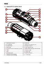
Page 11: ... Fixed electrical connectors 11 Electric fan air cooled versions only 3 EC marking plate 12 Pneumatic connectors 4 Serial number 13 Cover of the sensor area 5 Connector for sensor on accessories e g C axis 14 Button for the manual release of the tool holder 6 Nose 15 Pneumatic cylinder 7 Shaft 16 Resting surface 8 Tool hooking system 17 Seat for centring tang 9 Threaded bores for accessories on th...

Page 12: ...IN PARTS OF MODELS ES884 ES888 1 2 7 5 12 3 9 10 1 8 8 6 4 11 1 Sensor area 7 Pneumatic connections 2 Pneumatic cylinder 8 M6 threaded bores for accessories 3 Nose 9 Shaft 4 Fixing surface 10 Tool hooking system 5 Pressurisation connector 11 Serial number 6 Framework 12 Electrical connectors ...

Page 13: ...e 11 Electric fan air cooled versions only 3 Encoder connector 12 Pneumatic connectors 4 Serial number 13 Cover of the sensor area 5 Connector for sensor on accessories e g C axis 14 Button for the manual release of the tool holder 6 Nose 15 Pneumatic cylinder 7 Shaft 16 Resting surface 8 Tool hooking system 17 Seat for centring tang 9 Threaded bores for accessories on the sides and the front flan...

Page 14: ...ed electrical connectors 11 Electric fan air cooled versions only 3 Button for the manual release of the tool holder 12 Pneumatic connectors 4 Serial number 13 Cover of the sensor area 5 Connector for sensor on accessories e g C axis 14 Pneumatic cylinder 6 Nose 15 Resting surface 7 Shaft 16 Seat for centring tang 8 Tool hooking system 17 T slot for fixing 9 Threaded bores for accessories on the s...

Page 15: ...nnectors 2 EC marking plate 11 Cover of the sensor area 3 Serial number 12 Motor cooling liquid inlet outlet 4 Connector for sensor on accessories e g C axis 13 Pneumatic cylinder 5 Nose 14 Button for the manual release of the tool holder 6 Shaft 15 Resting surface 7 Tool hooking system 16 Seat for centring tang 8 Threaded bores for accessories on the sides and the front flange 17 T slot for fixin...

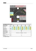
Page 16: ...8 000 Duty type S1 cont S6 60 S1 cont S6 60 S1 cont S6 60 S1 cont S6 60 Rated power kW 16 0 18 0 16 0 18 0 11 0 13 0 8 0 10 0 Rated torque Nm 19 21 5 15 3 17 2 7 0 8 3 4 2 5 3 Rated current A 34 5 45 34 5 45 23 7 32 6 18 0 26 0 Rated output η 0 8 Power factor cos φ 0 7 Number of poles 4 Type of insulation F IP rating 54 Type of cooling Raffreddamento a liquido Flüssigkeit Liquid cooling Weight of ...

Page 17: ...leerlaufstrom A 11 Resistenza dello statore stator resistance standerwiderstand kalt 20 C Ω 0 12 Resistenza del rotore rotor resistance lauferwiderstand kalt 20 C Ω 0 2 Reattanza di dispersione dello statore stator leakage reactance standerstreureaktanz Ω 1 Reattanza di dispersione del rotore rotor leakage reactance lauferstreureaktanz Ω 1 7 Reattanza del campo principale main field reactance haup...

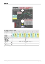
Page 18: ...000 Duty type S1 cont S6 60 S1 cont S6 60 S1 cont S6 60 S1 cont S6 60 S1 cont S6 60 S1 cont S6 60 Rated power kW 16 18 16 18 8 10 6 2 7 6 4 3 5 2 2 5 2 8 Rated torque Nm 19 21 5 15 3 17 2 4 2 5 3 3 3 6 1 9 2 3 1 0 1 1 Rated current A 34 5 45 34 5 45 18 26 14 3 17 2 8 11 4 6 5 Rated output η 0 8 Power factor cos φ 0 7 Number of poles 4 Type of insulation F IP rating 54 Type of cooling Raffreddament...

Page 19: ...leerlaufstrom A 11 Resistenza dello statore stator resistance standerwiderstand kalt 20 C Ω 0 12 Resistenza del rotore rotor resistance lauferwiderstand kalt 20 C Ω 0 2 Reattanza di dispersione dello statore stator leakage reactance standerstreureaktanz Ω 1 Reattanza di dispersione del rotore rotor leakage reactance lauferstreureaktanz Ω 1 7 Reattanza del campo principale main field reactance haup...

Page 20: ...pe S1 cont S6 60 S1 cont S6 60 S1 cont S6 60 S1 cont S6 60 S1 cont S6 60 S1 cont S6 60 S1 cont S6 60 S1 cont S6 60 Rated power kW 3 8 4 6 3 8 4 6 3 8 4 6 3 8 4 6 3 8 4 6 3 8 4 6 3 8 4 6 3 8 4 6 Rated torque Nm 3 3 7 1 8 2 2 1 5 1 8 1 3 1 6 3 3 7 1 8 2 2 1 5 1 8 1 3 1 6 Rated current A 8 3 10 8 3 10 8 3 10 8 3 10 14 4 17 3 14 4 17 3 14 4 17 3 14 4 17 3 Rated output η 0 8 Power factor cosϕ 0 8 Numbe...

Page 21: ...ente a vuoto no load current leerlaufstrom A 2 6 Resistenza dello statore stator resistance standerwiderstand kalt 20 C Ω 0 67 Resistenza del rotore rotor resistance lauferwiderstand kalt 20 C Ω 0 65 Reattanza di dispersione dello statore stator leakage reactance standerstreureaktanz Ω 2 1 Reattanza di dispersione del rotore rotor leakage reactance lauferstreureaktanz Ω 3 8 Reattanza del campo pri...

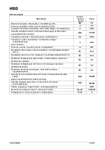
Page 22: ...ype S1 cont S6 60 S1 cont S6 60 S1 cont S6 60 S1 cont S6 60 S1 cont S6 60 Rated power kW 5 6 5 6 3 9 4 6 3 3 5 2 1 2 4 Rated torque Nm 4 4 8 3 2 3 8 1 7 2 2 1 2 1 4 0 7 0 8 Rated current A 12 14 10 5 14 9 2 10 5 7 8 4 4 5 Rated output η 0 86 Power factor cosϕ 0 82 Number of poles 4 Type of insulation F Type of cooling Elettroventola Elektrolüfter Cooling fan Weight of SHORT NOSE version kg 21 Weig...

Page 23: ...erlaufstrom A 4 3 Resistenza dello statore stator resistance standerwiderstand kalt 20 C Ω 0 27 Resistenza del rotore rotor resistance lauferwiderstand kalt 20 C Ω 0 24 Reattanza di dispersione dello statore stator leakage reactance standerstreureaktanz Ω 1 6 Reattanza di dispersione del rotore rotor leakage reactance lauferstreureaktanz Ω 3 2 Reattanza del campo principale main field reactance ha...

Page 24: ...pe S1 cont S6 50 S1 cont S6 50 S1 cont S6 50 S1 cont S6 50 S1 cont S6 50 S1 cont S6 50 Rated power kW 6 5 7 5 6 5 7 5 6 1 6 7 5 8 6 4 5 5 6 3 3 Rated torque Nm 5 2 6 4 1 4 8 3 2 3 6 2 8 3 1 2 4 2 6 1 1 Rated current A 15 18 15 18 14 15 7 13 16 13 1 14 1 7 5 7 5 Rated output η 0 82 Power factor cosϕ 0 74 Number of poles 4 Type of insulation F Type of cooling Raffreddamento a liquido Flüssigkeit Liq...

Page 25: ... leerlaufstrom A 4 3 Resistenza dello statore stator resistance standerwiderstand kalt 20 C Ω 0 27 Resistenza del rotore rotor resistance lauferwiderstand kalt 20 C Ω 0 24 Reattanza di dispersione dello statore stator leakage reactance standerstreureaktanz Ω 1 6 Reattanza di dispersione del rotore rotor leakage reactance lauferstreureaktanz Ω 3 2 Reattanza del campo principale main field reactance...

Page 26: ...ed speed rpm 7000 12 000 18 000 Duty type S1 cont S6 60 S1 cont S6 60 S1 cont S6 60 Rated power kW 5 5 6 6 4 5 5 4 1 5 1 8 Nm 7 5 9 3 6 4 3 0 8 1 Rated current A 15 18 14 17 6 5 8 Rated output η 0 8 Power factor cosϕ 0 8 Number of poles 4 Type of insulation F Type of cooling Elettroventola Elektrolüfter Cooling fan Weight of SHORT NOSE version kg 26 Weight of LONG NOSE version kg 31 supplied by in...

Page 27: ...rlaufstrom A 4 2 Resistenza dello statore stator resistance standerwiderstand kalt 20 C Ω 0 38 Resistenza del rotore rotor resistance lauferwiderstand kalt 20 C Ω 0 4 Reattanza di dispersione dello statore stator leakage reactance standerstreureaktanz Ω 3 4 Reattanza di dispersione del rotore rotor leakage reactance lauferstreureaktanz Ω 2 6 Reattanza del campo principale main field reactance haup...

Page 28: ...cont S6 60 S1 cont S6 60 S1 cont S6 60 S1 cont S6 60 S1 cont S6 60 S1 cont S6 60 Rated power kW 7 5 9 7 5 9 6 6 8 6 7 3 5 8 6 7 5 5 6 4 2 5 3 3 6 4 7 Rated torque Nm 6 7 2 4 8 5 7 3 5 4 2 2 9 3 5 2 5 2 9 2 2 2 4 1 5 2 1 2 1 6 Rated current A 20 22 5 17 20 5 16 18 5 15 17 5 13 15 13 14 10 12 6 11 5 15 Rated output η 0 85 Power factor cosϕ 0 8 Number of poles 4 Type of insulation F Type of cooling E...

Page 29: ... V 360 Corrente a vuoto no load current leerlaufstrom A 12 Resistenza dello statore stator resistance standerwiderstand kalt 20 C Ω 0 12 Resistenza del rotore rotor resistance lauferwiderstand kalt 20 C Ω 0 14 Reattanza di dispersione dello statore stator leakage reactance standerstreureaktanz Ω 1 2 Reattanza di dispersione del rotore rotor leakage reactance lauferstreureaktanz Ω 1 9 Reattanza del...

Page 30: ...000 28 000 Duty type S1 cont S6 60 S1 cont S6 60 S1 cont S6 60 S1 cont S6 60 S1 cont S6 60 S1 cont S6 60 S1 cont S6 60 S1 cont S6 60 Rated power kW 6 6 7 6 6 7 6 6 7 5 5 5 6 6 7 6 6 7 6 6 7 5 5 5 Rated torque Nm 5 3 5 6 3 2 3 3 2 6 2 8 1 7 1 9 5 3 5 6 3 2 3 3 2 6 2 8 1 7 1 9 Rated current A 15 8 18 15 8 18 15 8 18 15 17 27 4 31 2 27 4 31 2 27 4 31 2 26 29 4 Rated output η 0 8 Power factor cosϕ 0 8...

Page 31: ...urrent leerlaufstrom A 17 Resistenza dello statore stator resistance standerwiderstand kalt 20 C Ω 0 07 Resistenza del rotore rotor resistance lauferwiderstand kalt 20 C Ω 0 09 Reattanza di dispersione dello statore stator leakage reactance standerstreureaktanz Ω 0 29 Reattanza di dispersione del rotore rotor leakage reactance lauferstreureaktanz Ω 0 6 Reattanza del campo principale main field rea...

Page 32: ...rrent leerlaufstrom A 10 Resistenza dello statore stator resistance standerwiderstand kalt 20 C Ω 0 2 Resistenza del rotore rotor resistance lauferwiderstand kalt 20 C Ω 0 28 Reattanza di dispersione dello statore stator leakage reactance standerstreureaktanz Ω 0 87 Reattanza di dispersione del rotore rotor leakage reactance lauferstreureaktanz Ω 1 8 Reattanza del campo principale main field react...

Page 33: ...ont S6 60 S1 cont S6 60 S1 cont S6 60 S1 cont S6 60 S1 cont S6 60 S1 cont S6 60 S1 cont S6 60 S1 cont S6 60 S1 cont S6 60 S1 cont S6 60 Rated power kW 6 6 8 6 6 8 6 6 8 5 5 5 4 2 4 3 6 6 8 6 6 8 6 6 8 5 5 5 4 2 4 3 Rated torque Nm 5 3 6 4 3 2 3 8 2 6 3 2 1 7 1 9 1 3 1 4 5 3 6 4 3 2 3 8 2 6 3 2 1 7 1 9 1 3 1 4 Rated current A 15 8 18 15 8 18 15 8 18 15 17 12 3 13 4 27 4 31 2 27 4 31 2 27 4 31 2 26 ...

Page 34: ...urrent leerlaufstrom A 17 Resistenza dello statore stator resistance standerwiderstand kalt 20 C Ω 0 07 Resistenza del rotore rotor resistance lauferwiderstand kalt 20 C Ω 0 09 Reattanza di dispersione dello statore stator leakage reactance standerstreureaktanz Ω 0 29 Reattanza di dispersione del rotore rotor leakage reactance lauferstreureaktanz Ω 0 6 Reattanza del campo principale main field rea...

Page 35: ...rrent leerlaufstrom A 10 Resistenza dello statore stator resistance standerwiderstand kalt 20 C Ω 0 2 Resistenza del rotore rotor resistance lauferwiderstand kalt 20 C Ω 0 28 Reattanza di dispersione dello statore stator leakage reactance standerstreureaktanz Ω 0 87 Reattanza di dispersione del rotore rotor leakage reactance lauferstreureaktanz Ω 1 8 Reattanza del campo principale main field react...

Page 36: ...1 cont S6 60 S1 cont S6 60 S1 cont S6 60 S1 cont S6 60 S1 cont S6 60 Rated power kW 9 10 5 9 10 5 8 9 4 7 2 8 6 6 3 7 5 5 4 6 3 Rated torque Nm 7 2 8 7 5 7 6 7 4 2 5 3 4 4 1 2 7 3 3 2 2 2 5 Rated current A 21 25 3 19 2 22 5 17 5 20 15 8 19 14 17 12 9 14 7 Rated output η 0 85 Power factor cosϕ 0 85 Number of poles 4 Type of insulation F Type of cooling Elettroventola Elektrolüfter Cooling fan Weigh...

Page 37: ...rlaufstrom A 8 5 Resistenza dello statore stator resistance standerwiderstand kalt 20 C Ω 0 12 Resistenza del rotore rotor resistance lauferwiderstand kalt 20 C Ω 0 14 Reattanza di dispersione dello statore stator leakage reactance standerstreureaktanz Ω 1 2 Reattanza di dispersione del rotore rotor leakage reactance lauferstreureaktanz Ω 1 9 Reattanza del campo principale main field reactance hau...

Page 38: ... cont S6 60 S1 cont S6 60 S1 cont S6 60 S1 cont S6 60 S1 cont S6 60 Rated power kW 12 14 9 5 12 8 2 10 7 3 8 8 6 4 7 5 5 5 6 2 4 6 4 9 3 5 3 6 Rated torque Nm 9 5 11 1 6 7 6 4 6 5 3 3 5 4 2 2 8 3 3 2 2 2 5 1 7 1 8 1 2 1 2 Rated current A 27 5 32 22 26 4 16 5 20 17 20 5 16 5 19 14 15 7 11 8 12 5 8 9 9 2 Rated output η 0 86 Power factor cosϕ 0 8 Number of poles 4 Type of insulation F Type of cooling...

Page 39: ...eerlaufspannung bei nennflussu V 360 Corrente a vuoto no load current leerlaufstrom A 12 Resistenza dello statore stator resistance standerwiderstand kalt 20 C Ω 0 12 Resistenza del rotore rotor resistance lauferwiderstand kalt 20 C Ω 0 14 Reattanza di dispersione dello statore stator leakage reactance standerstreureaktanz Ω 1 2 Reattanza di dispersione del rotore rotor leakage reactance lauferstr...

Page 40: ...cont S6 60 S1 cont S6 60 S1 cont S6 60 S1 cont S6 60 S1 cont S6 60 S1 cont S6 60 S1 cont S6 60 Rated power kW 7 5 9 10 12 10 12 9 10 8 7 5 9 6 8 8 3 6 7 5 5 8 6 8 5 6 Rated torque Nm 10 2 12 3 8 9 6 6 3 7 6 4 8 5 7 3 6 4 3 3 3 6 2 4 3 2 1 2 5 1 7 2 1 Rated current A 27 32 4 20 24 20 24 19 22 8 14 5 17 4 13 3 16 13 15 6 12 3 14 1 10 7 12 7 Rated output η 0 90 Power factor cosϕ 0 74 Number of poles ...

Page 41: ...ent leerlaufstrom A 8 5 Resistenza dello statore stator resistance standerwiderstand kalt 20 C Ω 0 15 Resistenza del rotore rotor resistance lauferwiderstand kalt 20 C Ω 0 1 Reattanza di dispersione dello statore stator leakage reactance standerstreureaktanz Ω 0 58 Reattanza di dispersione del rotore rotor leakage reactance lauferstreureaktanz Ω 1 Reattanza del campo principale main field reactanc...

Page 42: ...S1 cont S6 60 S1 cont S6 60 S1 cont S6 60 S1 cont S6 60 S1 cont S6 60 Rated power kW 16 18 14 16 12 14 10 8 12 7 9 5 11 3 8 2 10 7 8 7 5 6 7 3 Rated torque Nm 12 7 14 3 8 9 10 2 6 4 7 4 5 2 6 1 4 1 4 9 3 3 4 0 2 6 3 2 1 9 2 5 Rated current A 31 35 5 27 6 31 23 27 21 25 18 5 22 15 8 20 14 17 11 15 Rated output η 0 90 Power factor cosϕ 0 79 Number of poles 4 Type of insulation F Type of cooling Raff...

Page 43: ...aufstrom A 7 7 Resistenza dello statore stator resistance standerwiderstand kalt 20 C Ω 0 15 Resistenza del rotore rotor resistance lauferwiderstand kalt 20 C Ω 0 08 Reattanza di dispersione dello statore stator leakage reactance standerstreureaktanz Ω 0 6 Reattanza di dispersione del rotore rotor leakage reactance lauferstreureaktanz Ω 1 1 Reattanza del campo principale main field reactance haupt...

Page 44: ...6 60 S1 cont S6 60 S1 cont S6 60 S1 cont S6 60 S1 cont S6 60 S1 cont S6 60 S1 cont S6 60 Rated power kW 7 5 9 10 12 10 12 9 10 8 7 5 9 6 7 5 5 3 6 8 Rated torque Nm 10 2 12 3 8 9 6 6 3 7 6 4 8 5 7 3 6 4 3 2 4 3 1 9 2 5 Rated current A 27 32 4 20 24 20 24 19 22 8 14 5 17 4 13 15 6 11 3 14 5 Rated output η 0 90 Power factor cosϕ 0 74 Number of poles 4 Type of insulation F Type of cooling Elettrovent...

Page 45: ...nt leerlaufstrom A 8 5 Resistenza dello statore stator resistance standerwiderstand kalt 20 C Ω 0 15 Resistenza del rotore rotor resistance lauferwiderstand kalt 20 C Ω 0 1 Reattanza di dispersione dello statore stator leakage reactance standerstreureaktanz Ω 0 58 Reattanza di dispersione del rotore rotor leakage reactance lauferstreureaktanz Ω 1 Reattanza del campo principale main field reactance...

Page 46: ...S6 60 S1 cont S6 60 S1 cont S6 60 S1 cont S6 60 S1 cont S6 60 Rated power kW 16 18 12 14 10 8 12 7 8 2 10 7 8 7 Rated torque Nm 12 7 14 3 6 4 7 4 5 2 6 1 3 3 4 0 2 6 3 2 Rated current A 31 35 5 23 27 21 25 15 8 20 14 17 Rated output η 0 90 Power factor cosϕ 0 79 Number of poles 4 Type of insulation F Type of cooling Raffreddamento a liquido Flüssigkeit Liquid cooling Weight of SHORT NOSE version k...

Page 47: ...laufstrom A 7 7 Resistenza dello statore stator resistance standerwiderstand kalt 20 C Ω 0 15 Resistenza del rotore rotor resistance lauferwiderstand kalt 20 C Ω 0 08 Reattanza di dispersione dello statore stator leakage reactance standerstreureaktanz Ω 0 6 Reattanza di dispersione del rotore rotor leakage reactance lauferstreureaktanz Ω 1 1 Reattanza del campo principale main field reactance haup...

Page 48: ...t S6 60 S1 cont S6 60 S1 cont S6 60 S1 cont S6 60 Rated power kW 7 5 8 6 7 0 8 1 5 5 6 3 4 5 5 2 Rated torque Nm 11 9 13 7 5 6 6 4 2 9 3 3 1 8 2 1 Rated current A 15 5 17 8 15 0 19 3 11 5 13 2 10 0 11 5 Rated output η 0 88 0 86 0 80 0 75 Power factor cosϕ 0 8 Number of poles 4 Type of insulation F Type of cooling Elettroventola Elektrolüfter Cooling fan Weight of SHORT NOSE version kg 26 Weight of...

Page 49: ...te a vuoto no load current leerlaufstrom A 5 6 Resistenza dello statore stator resistance standerwiderstand kalt 20 C Ω 0 5 Resistenza del rotore rotor resistance lauferwiderstand kalt 20 C Ω 0 48 Reattanza di dispersione dello statore stator leakage reactance standerstreureaktanz Ω 1 0 Reattanza di dispersione del rotore rotor leakage reactance lauferstreureaktanz Ω 1 7 Reattanza del campo princi...

Page 50: ...t S6 40 S1 cont S6 40 S1 cont S6 40 S1 cont S6 40 Rated power kW 9 10 8 9 6 6 5 4 5 5 2 Rated torque Nm 14 3 15 9 6 4 7 2 3 2 3 4 1 8 2 1 Rated current A 18 6 20 7 17 1 21 7 12 7 13 6 10 11 5 Rated output η 0 88 0 86 0 80 0 75 Power factor cosϕ 0 8 Number of poles 4 Type of insulation F Type of cooling Raffreddamento a liquido Flüssigkeit Liquid cooling Weight of SHORT NOSE version kg 30 Weight of...

Page 51: ...te a vuoto no load current leerlaufstrom A 5 6 Resistenza dello statore stator resistance standerwiderstand kalt 20 C Ω 0 5 Resistenza del rotore rotor resistance lauferwiderstand kalt 20 C Ω 0 48 Reattanza di dispersione dello statore stator leakage reactance standerstreureaktanz Ω 1 0 Reattanza di dispersione del rotore rotor leakage reactance lauferstreureaktanz Ω 1 7 Reattanza del campo princi...

Page 52: ...S1 cont S6 60 S1 cont S6 60 S1 cont S6 60 S1 cont S6 60 S1 cont S6 60 S1 cont S6 60 Rated power kW 8 11 13 5 11 13 5 8 9 10 2 7 5 8 6 5 7 5 5 6 Rated torque Nm 10 9 8 8 10 7 7 0 8 6 4 7 5 4 3 6 3 8 2 8 3 2 2 2 4 Rated current A 32 25 6 31 5 26 2 32 25 4 30 18 6 19 8 17 5 21 8 14 17 4 Rated output η 0 86 Power factor cosϕ 0 88 Number of poles 4 Type of insulation F Type of cooling Elettroventola El...

Page 53: ... 364 Corrente a vuoto no load current leerlaufstrom A 9 5 Resistenza dello statore stator resistance standerwiderstand kalt 20 C Ω 0 09 Resistenza del rotore rotor resistance lauferwiderstand kalt 20 C Ω 0 13 Reattanza di dispersione dello statore stator leakage reactance standerstreureaktanz Ω 0 61 Reattanza di dispersione del rotore rotor leakage reactance lauferstreureaktanz Ω 1 8 Reattanza del...

Page 54: ...pm 12 000 15 000 20 000 Duty type S1 cont S6 60 S1 cont S6 60 S1 cont S6 60 Rated power kW 15 17 15 17 8 15 5 Rated torque Nm 12 13 5 9 6 10 8 3 8 7 4 Rated current A 34 40 34 40 19 39 Rated output η 0 86 Power factor cosϕ 0 82 Number of poles 4 Type of insulation F Type of cooling Raffreddamento a liquido Flüssigkeit Liquid cooling Weight of LONG NOSE version kg 45 supplied by inverter ...

Page 55: ...V 364 Corrente a vuoto no load current leerlaufstrom A 9 5 Resistenza dello statore stator resistance standerwiderstand kalt 20 C Ω 0 09 Resistenza del rotore rotor resistance lauferwiderstand kalt 20 C Ω 0 13 Reattanza di dispersione dello statore stator leakage reactance standerstreureaktanz Ω 0 61 Reattanza di dispersione del rotore rotor leakage reactance lauferstreureaktanz Ω 1 8 Reattanza de...

Page 56: ...6 60 S1 cont S6 60 S1 cont S6 60 S1 cont S6 60 S1 cont S6 60 Rated power kW 16 0 18 0 16 0 18 0 11 0 13 0 8 0 10 0 4 3 5 2 Rated torque Nm 19 21 5 15 3 17 2 7 0 8 3 4 2 5 3 1 9 2 3 Rated current A 34 5 45 34 5 45 23 7 32 6 18 0 26 0 8 0 11 0 Rated output η 0 8 Power factor cos φ 0 7 Number of poles 4 0 Type of insulation F IP rating 54 Type of cooling Raffreddamento a liquido Flüssigkeit Liquid co...

Page 57: ...leerlaufstrom A 11 Resistenza dello statore stator resistance standerwiderstand kalt 20 C Ω 0 12 Resistenza del rotore rotor resistance lauferwiderstand kalt 20 C Ω 0 2 Reattanza di dispersione dello statore stator leakage reactance standerstreureaktanz Ω 1 Reattanza di dispersione del rotore rotor leakage reactance lauferstreureaktanz Ω 1 7 Reattanza del campo principale main field reactance haup...

Page 58: ... 000 6000 12 000 Duty type S1 cont S6 60 S1 cont S6 60 S1 cont S6 60 S1 cont S6 60 Rated power kW 7 8 5 6 7 8 5 6 Rated torque Nm 11 1 12 7 8 8 2 11 1 12 7 8 8 2 Rated current A 28 32 21 26 14 16 10 5 13 Rated output η 0 88 Power factor cosϕ 0 82 Number of poles 4 Type of insulation F Type of cooling Raffreddamento a liquido Flüssigkeit Liquid cooling Weight of LONG NOSE version kg 39 supplied by ...

Page 59: ...current leerlaufstrom A 4 Resistenza dello statore stator resistance standerwiderstand kalt 20 C Ω 0 43 Resistenza del rotore rotor resistance lauferwiderstand kalt 20 C Ω 0 57 Reattanza di dispersione dello statore stator leakage reactance standerstreureaktanz Ω 1 9 Reattanza di dispersione del rotore rotor leakage reactance lauferstreureaktanz Ω 6 0 Reattanza del campo principale main field reac...

Page 60: ...rrent leerlaufstrom A 7 9 Resistenza dello statore stator resistance standerwiderstand kalt 20 C Ω 0 11 Resistenza del rotore rotor resistance lauferwiderstand kalt 20 C Ω 0 14 Reattanza di dispersione dello statore stator leakage reactance standerstreureaktanz Ω 0 7 Reattanza di dispersione del rotore rotor leakage reactance lauferstreureaktanz Ω 1 5 Reattanza del campo principale main field reac...

Page 61: ... cont S6 60 S1 cont S6 60 S1 cont S6 60 S1 cont S6 60 S1 cont S6 60 S1 cont S6 60 Rated power kW 8 9 11 5 4 7 1 4 6 3 5 2 3 9 Rated torque Nm 10 9 8 2 10 2 9 3 8 1 9 2 9 1 3 2 2 0 8 1 6 Rated current A 27 5 20 5 25 12 15 6 12 18 5 9 15 5 6 12 Rated output η 0 8 Power factor cosϕ 0 8 Number of poles 4 Type of insulation F Type of cooling Elettroventola Elektrolüfter Cooling fan Weight of SHORT NOSE...

Page 62: ...erlaufstrom A 6 0 Resistenza dello statore stator resistance standerwiderstand kalt 20 C Ω 0 14 Resistenza del rotore rotor resistance lauferwiderstand kalt 20 C Ω 0 22 Reattanza di dispersione dello statore stator leakage reactance standerstreureaktanz Ω 1 1 Reattanza di dispersione del rotore rotor leakage reactance lauferstreureaktanz Ω 1 8 Reattanza del campo principale main field reactance ha...

Page 63: ... S1 cont S6 60 S1 cont S6 60 S1 cont S6 60 S1 cont S6 60 S1 cont S6 60 Rated power kW 8 11 13 5 11 13 5 8 9 10 2 7 5 8 6 5 7 5 5 6 Rated torque Nm 10 9 8 8 10 7 7 0 8 6 4 7 5 4 3 6 3 8 2 8 3 2 2 2 4 Rated current A 32 25 6 31 5 26 2 32 25 4 30 18 6 19 8 17 5 21 8 14 17 4 Rated output η 0 86 Power factor cosϕ 0 88 Number of poles 4 Type of insulation F Type of cooling Elettroventola Elektrolüfter C...

Page 64: ...V 364 Corrente a vuoto no load current leerlaufstrom A 9 5 Resistenza dello statore stator resistance standerwiderstand kalt 20 C Ω 0 09 Resistenza del rotore rotor resistance lauferwiderstand kalt 20 C Ω 0 13 Reattanza di dispersione dello statore stator leakage reactance standerstreureaktanz Ω 0 61 Reattanza di dispersione del rotore rotor leakage reactance lauferstreureaktanz Ω 1 8 Reattanza de...

Page 65: ...dimensions of the packaging shown in the accompanying documents 3 3 TRANSPORT AND PACKAGING CONDITIONS The product is shipped protected by a covering of VCI plastic and expanded foam packed in a wooden crate or case of special cardboard The figure shows a few methods of lifting the packed product using ropes and a fork lift truck in the latter case ensure that during lifting the centre of gravity ...

Page 66: ...o carry out periodic checks to ensure the good general condition of conservation to manually rotate the shaft roughly once a month to maintain optimum lubrication of the bearings STORAGE TEMPERATURE from 5 C 41 F to 55 C 131 F RELATIVE HUMIDITY NON CONDENSING from 5 to 55 i Maximum storage time for an HSD product is 12 months Beyond this limit it is necessary to review the state of the product For...

Page 67: ...ricity supply as far as the connectors of the electrospindle The customer is also reminded of the need to provide all the safety conditions necessary for the earthing of the electrospindle The earthing system must conform to the standards in force in the country of installation and must be inspected at regular intervals by qualified personnel For the connections see the sections below 4 3 MECHANIC...

Page 68: ...indle is fixed must have a planarity of less than 0 02mm r 0 02 4 3 3 Fixing structure for spindles with round framework i The fixing structure on which the electrospindle is to be fitted must have a planarity of less than 0 015mm and a perpendicularity with respect to the spindle axis of less than 0 015mm r 0 015 n A 0 015 1 Electrospindle fixing structure 2 Electrospindle A n A 0 015 r 0 015 1 2...

Page 69: ... cone ISO 30 3 Spindle shaft HSK F63 4 Tool holder cone HSK F63 B a B A a A ISO HSK 1 3 4 2 C C The tool holder magazine must position the cones with a concentricity error between the spindle shaft and the tool holder cone as shown in the table below Tool hooking system Concentricity C mm ISO 30 0 2 HSK E50 F63 0 8 HSK E40 F50 0 7 HSK E63 F80 0 8 ...

Page 70: ...t alignment use the tang slot between the two T slots see section 2 80 100 5 10 8 16 16 5 Figure4 2 T slots for anchoring the electrospindle 16 15 MAX 1 MIN Figure4 3 Maximum protrusion of the screw in the T slot Maximum protrusion of the screw 15mm Ensure a gap of at least 1mm Greater protrusions deform the framework of the electrospindle compromising the precision of the machining operation and ...

Page 71: ...indicated in this section should be installed as near the electrospindle as possible taking into account the fact that the efficiency of the filters is 100 it is essential that the machine be fed with properly treated air As a general guide introduce into the circuit indicated in this section compressed air with a purity rating complying with ISO 8573 1 classes 7 6 4 i e o Type 7 for solid particl...

Page 72: ... with single acting cylinder Ref Description Pressure Ø Tube 1 Tool holder release 6 bar Ø 8 x 6 2 Pressurisation and cone cleaning 4 bar Ø 8 x 6 2 1 4 4 3 Variation with vertical block single acting cylinder Ref Description Pressure Ø Tube 1 Tool holder release 6 7 bar Ø 8 x 6 2 Pressurisation and cone cleaning 6 7 bar Ø 8 x 6 1 2 ...

Page 73: ...r input for tool holder release 8 Air input for cone cleaning and pressurisation 9 Pneumatic circuit inside the electrospindle 10 Single acting pneumatic cylinder 11 Valve to activate the cone cleaning piston commanded 12 Throat 13 Continuous flow of pressurisation air Use two separate circuits to connect the electric valves to the numerical control The use of two electric valves in series instead...

Page 74: ...tion Pressure Ø Tube 1 Tool holder hook up 6 bar Ø 8 x 6 2 Pressurisation 4 bar Ø 4x2 3 Tool holder release 6 bar Ø 8 x 6 4 Cone cleaning all versions Air inside tool optional MAX 4 bar Ø 8 x 6 2 3 4 1 The cylinders of these electrospindles are double acting it is necessary to keep the cylinder under pressure to maintain the piston at the upper end stop far from the fast rotating parts ...

Page 75: ... 5 Monostable valve 5 2 with electro pneumatic command and spring return 6 Air inlet for tool holder release 7 Quick bleeder valve 8 One way flow regulator to adjust ejection speed 9 Air inlet for tool holder hook up 10 Double acting pneumatic cylinder of the electrospindle 11 Monostable valve 3 1 with electro pneumatic command and spring return 12 Air inlet for cone cleaning in all versions and f...

Page 76: ..._________ 76 181 4 4 5 Pneumatic connection points for spindles ES884 ES888 single acting cylinder Ref Description Pressure Ø Tube 1 Tool holder release 10 bar Ø 6x4 2 Cone cleaning 4 bar Ø 6x4 3 Pressurisation 4 bar Ø 4x2 4 Cooling liquid inlet ouput Ø 8 x 6 2 3 1 4 4 ...

Page 77: ...ut for tool holder release 8 Air inlet for cone cleaning 9 Air inlet for pressurisation 10 Pneumatic circuit inside the electrospindle 11 Single acting pneumatic cylinder 12 Valve to activate the cone cleaning piston commanded 13 Throat 14 Continuous flow of pressurisation air Use two separate circuits to connect the electric valves to the numerical control The use of two electric valves in series...

Page 78: ...e case check the efficiency of the pneumatic circuit and the tightness of the connections MODEL CONSUMPTION EQUIVALENT VOLUME 1 Atm 20 C 68 F ES915 12 l min 0 42 cfm 4 bar 20 C 68 F 48 l min 1 7 cfm ES919 12 l min 0 42 cfm 4 bar 20 C 68 F 48 l min 1 7 cfm ES988 12 l min 0 42 cfm 4 bar 20 C 68 F 48 l min 1 7 cfm ES939 14 l min 0 49 cfm 4 bar 20 C 68 F 56 l min 2 0 cfm ES884 11 5 l min 0 40 cfm 4 ba...

Page 79: ...for use and tested by HSD S p A It contains monoethylene glycol and corrosion inhibitors based on an ecological formula and without amines nitrates or phosphates and ensures protection against corrosion for roughly 1 year ARTIC FLU 5 prevents the formation of rust scale and foam deposits as well as the hardening cracking or swelling of the seals and sleeves It complies with various international s...

Page 80: ...e mounting plates are available with cables of different lengths The position of the electrical connectors is shown in section 2 4 6 1 1 Layout of POWER connector fixed part PIN DESCRIPTION 1 Thermal alarm 230V AC MAX 48V DC MAX 1 6A MAX 2 Common PE with PIN 7 3 230V AC 50 60Hz solenoid valve if present 4 U Motor phase 5 Thermal alarm 230V AC MAX 48V DC MAX 1 6A MAX 2 5 3 4 6 1 8 9 7 6 Motor V pha...

Page 81: ...haft stopped optional 4 24V CC power supply S1 S2 S3 5 24V CC power supply bulb on the button 6 0V power supply S1 S2 S3 7 24V CC power supply to button and SC sensor C axis zero setting 8 Button OUTPUT 9 Not used 10 Not used 11 0V power supply BUTTON BULB and SC sensor 7 14 1 2 13 15 12 3 16 8 21 22 20 4 17 11 18 5 19 10 6 9 12 SC sensor OUTPUT zero setting C axis 13 Not used 14 For HSD maintenan...

Page 82: ...sor S3 shaft stopped optional 4 24V CC power supply S1 S2 S3 5 24V CC power supply bulb on the button 6 0V power supply S1 S2 S3 7 24V CC power supply to button and SC sensor C axis zero setting 8 Button OUTPUT 9 Not used 10 Not used 11 0V power supply BUTTON BULB and SC sensor 7 14 1 2 13 15 12 3 16 8 21 22 20 4 17 11 18 5 19 10 6 9 12 SC sensor OUTPUT zero setting C axis 13 Not used 14 For HSD m...

Page 83: ...C E F F 230V AC 50 60Hz solenoid valve if present 4 6 2 2 Sensors connector A S2 sensor tool ejected OUTPUT B S1 S4 sensor series tool locked OUTPUT C OUTPUT sensor S3 shaft stopped D 24V CC power supply sensors S1 S2 S3 E 24V CC power supply to lamp of button F 0V power supply sensors S1 S2 S3 S4 G 24V CC power supply to button and sensor SC H OUTPUT button J 0V power supply to lamp of button and...

Page 84: ...f the terminal board is shown alongside protected by a cover fixed with two screws Before installing check the type of connection in the terminal board CONNECTIONS LAYOUT STAR CONNECTION rated voltage 380V DELTA CONNECTION rated voltage 220V RED STATOR 380V PIN6 BLACK STATOR WHITE STATOR BLACK STATOR WHITE STATOR RED STATOR 380V PIN4 380V PIN8 BLACK STATOR WHITE STATOR RED STATOR RED STATOR 220V P...

Page 85: ... Power connector A U motor phase B V motor phase C W motor phase D Earth connection E 230V AC 50 60Hz electric fan A B D C E F F 230V AC 50 60Hz electric fan 4 6 4 2 Sensors connector A S2 sensor tool ejected OUTPUT B S1 S4 sensor series tool locked OUTPUT C OUTPUT sensor S3 shaft stopped D 24V CC power supply sensors S1 S2 S3 E 24V CC power supply to lamp of button F 0V power supply sensors S1 S2...

Page 86: ...ated current 29 mA 4 7 1 Electrical layout for tool holder manual release circuit When the spindle is rotating a control system must deactivate the command arriving from the button The activation of the button must only be possible with the spindle idle The tool block release operation via the button must only be carried out with the machine in MANUAL working mode not AUTOMATIC The tool could be e...

Page 87: ...aximum voltage set on the inverter must correspond to the rated value indicated on the motor rating plate The frequency value at which the maximum voltage rated frequency is to be attained must correspond to the value indicated on the motor rating plate The maximum speed set on the inverter must correspond to the value indicated on the motor rating plate The maximum direct current supplied to the ...

Page 88: ... the machine is switched on for the first time every day allow the electrospindle to perform a brief preheating cycle in order to allow the bearings to gradually attain a uniform operating temperature and hence to obtain a uniform expansion of the bearing races and the correct preload and rigidity The following cycle is recommended without machining operations 50 of the maximum rated speed for 2 m...

Page 89: ... 000 cycles of tool change 1 tool change cycle tool blocked tool released tool blocked i All HSD electrospindles have a mechanical reaction system that neutralises the axial force of the piston on the shaft during the tool changing phase guaranteeing the integrity of the precision bearings 6 6 TOOL HOLDER CONE Figure 6 1 CONE ISO30 DIN69871 HSD TIE ROD 0804H0009 Figure 6 2 HSK DIN69893 CONE The ge...

Page 90: ...achining operations be sure to avoid any contact between the non cutting rotating parts and the piece being machined The seat of the tool holder cone must always be protected against any impurity that may come in use a closing device or a tool holder cone At the end of the working day always remove the tool holder cone from the electrospindle to avoid any problem of it sticking Replace it with a c...

Page 91: ... centre of gravity G of the tool tool holder assembly Next to each chart there is the tool tool holder assembly that was envisaged as assembled in the spindle shaft to calculate the curves The mass of the tool tool holder assembly was applied to the centre of gravity G highlighted in the design Some possible positions of the centre of gravity G were considered and for each position a curve has bee...

Page 92: ...gravity b relative position of the centre of gravity V volume m mass d density in the absence of data supplied by the toolmaker use the following general densities Iron 7850kg m3 Aluminium 2100kg m3 3 Elementary formulas for calculating the centre of gravity 3 1 Cylindrical segment possibly cable h 2 Posizione G b Massa m Vd Volume V π r2 r1 h 2 h b G r1 r2 3 2 Conical segment h r2 2r2r1 3r1 2 4 r...

Page 93: ...sition of the centre of gravity of the assembly starting from the centres of gravity of the individual parts m1x1 m2x2 m3x3 m4x4 X m1 m2 m3 m4 in yellow the reference faces for measuring b b1 G1 x1 x2 x3 x4 G b2 b3 b3 G2 G3 G4 X 5 Use the value X to choose the right curve of the chart x G G G G x xxx ...

Page 94: ...the tool tool holder assembly read the value of the maximum speed 4 If the weight or the distance of G are greater than those envisaged by HSD it will be the user s responsibility to evaluate each time the maximum speed that allows him to work safely i If you are concerned that the tool is too big and could damage the electrospindle contact HSD Customer Service EXAMPLE 1 On an ES929 L HSK F63 SHOR...

Page 95: ...ameter 100mm length 600mm and overall weight 20kg X G 600 100 1 b h 2 600 2 300mm 2 The tool is comparable with a single elementary part cylinder so X b 300mm 3 The chart relating to this particular electrospindle is that in paragraph 6 7 2 5 4 The length and weight of the tool are outside the charts calculated by HSD It will be the user s responsibility to evaluate the maximum speed at which to w...

Page 96: ..._____________________________________________________________ 96 181 6 7 2 3 ES915 HSK F63 Long Nose 6000 8000 10000 12000 14000 16000 18000 20000 22000 0 5 1 1 5 2 2 5 3 3 5 4 4 5 5 5 5 6 kg rpm X 70 X 90 X 110 X 130 ...

Page 97: ...______________________________________________________ 97 181 6 7 2 4 ES929 ISO30 Short Nose 0 1 1 5 2 2 5 3 3 5 4 4 5 5 5 5 6 0 2000 4000 6000 8000 10000 12000 14000 16000 18000 20000 22000 24000 Kg rpm X 50 X 70 X 90 X 110 ...

Page 98: ...______________________________________________________ 98 181 6 7 2 5 ES929 ISO30 Long Nose 0 1 1 5 2 2 5 3 3 5 4 4 5 5 5 5 6 0 2000 4000 6000 8000 10000 12000 14000 16000 18000 20000 22000 24000 Kg rpm X 50 X 70 X 90 X 110 ...

Page 99: ...____________________________________________________ 99 181 6 7 2 6 ES929 HSK F63 Short Nose 0 1 1 5 2 2 5 3 3 5 4 4 5 5 5 5 6 0 2000 4000 6000 8000 10000 12000 14000 16000 18000 20000 22000 24000 Kg rpm X 70 X 90 X 110 X 130 ...

Page 100: ...____________________________________________________ 100 181 6 7 2 7 ES929 HSK F63 Long Nose 0 1 1 5 2 2 5 3 3 5 4 4 5 5 5 5 6 0 2000 4000 6000 8000 10000 12000 14000 16000 18000 20000 22000 24000 Kg rpm X 70 X 90 X 110 X 130 ...

Page 101: ...__________________________________________ 101 181 6 7 2 8 ES915 ISO30 Short Nose 0 1 1 5 2 2 5 3 3 5 4 4 5 5 5 5 6 0 2000 4000 6000 8000 10000 12000 14000 16000 18000 20000 22000 24000 Peso Kg Utensile Portaut rpm X 50 X 70 X 90 X 110 ...

Page 102: ..._______________________________________ 102 181 6 7 2 9 ES919 ES939 ISO30 Short Nose 0 1 1 5 2 2 5 3 3 5 4 4 5 5 5 5 6 0 2000 4000 6000 8000 10000 12000 14000 16000 18000 20000 22000 24000 Peso Kg Utensile Portaut rpm X 50 X 70 X 90 X 110 ...

Page 103: ..._______________________________________ 103 181 6 7 2 10 ES919 ES939 ISO30 Long Nose 0 1 1 5 2 2 5 3 3 5 4 4 5 5 5 5 6 0 2000 4000 6000 8000 10000 12000 14000 16000 18000 20000 22000 24000 Peso Kg Utensile Portaut rpm X 50 X 70 X 90 X 110 ...

Page 104: ..._____________________________________ 104 181 6 7 2 11 ES919 ES939 HSK F63 Short Nose 0 1 1 5 2 2 5 3 3 5 4 4 5 5 5 5 6 0 2000 4000 6000 8000 10000 12000 14000 16000 18000 20000 22000 24000 Peso Kg Utensile Portaut rpm X 70 X 90 X 110 X 130 ...

Page 105: ..._____________________________________ 105 181 6 7 2 12 ES919 ES939 HSK F63 Long Nose 0 1 1 5 2 2 5 3 3 5 4 4 5 5 5 5 6 0 2000 4000 6000 8000 10000 12000 14000 16000 18000 20000 22000 24000 Peso Kg Utensile Portaut rpm X 70 X 90 X 110 X 130 ...

Page 106: ...___________________________________________ 106 181 6 7 2 13 ES983 HSK E63 Long Nose 0 1 1 5 2 2 5 3 3 5 4 4 5 5 5 5 6 6 5 7 0 2000 4000 6000 8000 10000 12000 14000 16000 18000 20000 Peso Kg Utensile Portaut rpm X 70 X 90 X 110 X 130 ...

Page 107: ..._______________________________________ 107 181 6 7 2 14 ES888 988 ISO 30 Short Nose 0 1 1 5 2 2 5 3 3 5 4 4 5 5 5 5 6 0 2000 4000 6000 8000 10000 12000 14000 16000 18000 20000 22000 24000 Peso Kg Utensile Portaut rpm X 50 X 70 X 90 X 110 ...

Page 108: ..._______________________________________ 108 181 6 7 2 15 ES888 988 ISO 30 Long Nose 0 1 1 5 2 2 5 3 3 5 4 4 5 5 5 5 6 0 2000 4000 6000 8000 10000 12000 14000 16000 18000 20000 22000 24000 Peso Kg Utensile Portaut rpm X 50 X 70 X 90 X 110 ...

Page 109: ..._________________________________________ 109 181 6 7 2 16 ES888 988 HSK F63 Short Nose 0 1 1 5 2 2 5 3 3 5 4 4 5 5 5 5 6 6 5 7 0 2000 4000 6000 8000 10000 12000 14000 16000 18000 20000 Peso Kg Utensile Portaut rpm X 70 X 90 X 110 X 130 ...

Page 110: ...___________________________________ 110 181 6 7 2 17 ES888 988 HSK F63 Long Nose 0 1 1 5 2 2 5 3 3 5 4 4 5 5 5 5 6 6 5 7 0 2000 4000 6000 8000 10000 12000 14000 16000 18000 20000 22000 24000 Peso Kg Utensile Portaut rpm X 70 X 90 X 110 X 130 ...

Page 111: ...do not move the spindle along the Z axis Z X Y If possible release the piece manually and then carry out the tool changing manually If this is not possible proceed in the following way Supply air to the tool changing circuit Slowly move the spindle away from the piece moving it along the Z axis until the collet opens ON output of sensor S2 Check the collet spindle has been freed from the collet Mo...

Page 112: ...ed owing to the force of the spring the collet will then shoot back violently perhaps breaking the tie rod N Description 1 ISO collet spindle 2 Spindle shaft 3 ISO collet or bush 4 Tie rod The arrows show the direction in which the blocking system moves after freeing the collet spindle 5 Point in which the collet knocks against the shaft 6 Breakage of the tie rod UTENSILE BLOCCATO IMPATTO 1 2 3 4 ...

Page 113: ...ne attached S2 Collet open S3 Shaft stopped S4 HSK cone blocked in correct position S5 Piston at upper end stop Thermal alarm Engine overheated stop the electrospindle Not present in certain versions In HSK versions only Only on models with double acting piston 6 9 1 Technical characteristics of the inductive sensors Type Proximity PNP normally open NO Supply voltage 10 30V DC Maximum load 200 mA ...

Page 114: ...he machine The shaft of the electrospindle can only be rotated in the Tool holder cone blocked correctly state if the outputs of S1 S5 or S1 S4 S5 move to OFF stop the electrospindle shaft rotation 6 9 3 Output of sensor S3 shaft idle signal Sensor S3 supplies two ON pulses and two OFF pulses at each rotation of the shaft as shown in the figure below 24 V 0 V 0 giri rev 1 i Above a certain speed r...

Page 115: ...ked the bearings of the spindle could break if you wait too long before moving the tool away from the piece and stopping the rotation the stator could be burnt 6 9 4 1 Technical characteristics of the bimetallic switch Power supply 48V DC MAX Current 1 6A MAX Switching cycles 10 000 cycles Contact breaking time 1 ms Contact resistance according to MIL R 5757 50 mΩ Insulation voltage 2 kV 6 10 ENCO...

Page 116: ...C 10 Consumption 99 mA with 12V DC 51 mA with 24V DC Operating temperature 0 C 70 C 32 F 158 F Max operating altitude 2000m 6500ft Signal input 400 pulses per rev zero reference Signal output TTL level compatible 0V 5V line driver 6 10 3 Output of the HSD Square Wave encoder D T 5 V Z Z 0 V 5 V 0 V 5 V 0 V 5 V 0 V B B A A 5 V 0 V 5 V 0 V 5 V 0 V 5 V 0 V 5 V 0 V 5 V 0 V T Period D Phase Difference ...

Page 117: ... VALUE Rated electrical power 5V DC 5 Operating temperature 30 C 85 C 22 F 185 F Max operating altitude 2000m 6500ft Signal input 512 pulses per rev zero reference 128 pulses multiplied internally by 4 Signals output TTL level compatible 0V 5V line driver 6 10 5 Output of the Lenord Bauer Square Wave encoder D T Z Z B B A A 5 V 0 V 5 V 0 V 5 V 0 V 5 V 0 V 5 V 0 V 5 V 0 V ...

Page 118: ... 185 F Max operating height 2000m 6500ft Signal input 128 pulses per rev zero reference A B signal output 500 mV peak to peak with average value U ref U 2 1 V peak to peak as difference of signals with average value U ref see figures below A B signal phase difference 90 a quarter of period Z signal output 500 mV peak compared with resting value U ref 80mV 1 V peak as difference of signals with res...

Page 119: ...HSD 5801H0056 ______________________________________________________________ 119 181 A signal temporal performance A 2 2 25 2 5 2 75 3 A 2 2 25 2 5 2 75 3 A diff A A 1 75 2 2 25 2 5 2 75 3 3 25 ...

Page 120: ...HSD 5801H0056 ______________________________________________________________ 120 181 A signal temporal performance B 2 2 25 2 5 2 75 3 B 2 2 25 2 5 2 75 3 B diff B B 1 75 2 2 25 2 5 2 75 3 3 25 ...

Page 121: ...HSD 5801H0056 ______________________________________________________________ 121 181 A signal temporal performance Z 2 2 25 2 5 2 75 3 Z 2 2 25 2 5 2 75 3 Z diff Z Z 1 75 2 2 25 2 5 2 75 3 3 25 3 5 ...

Page 122: ...HSD 5801H0056 ______________________________________________________________ 122 181 A and B signal phase difference 2 2 25 2 5 2 75 3 A B A and B negated signal phase difference 2 2 25 2 5 2 75 3 A B ...

Page 123: ...______________________________ 123 181 Differential signal temporal performance T Period D Phase Difference D T 4 A diff A A B diff B B Z diff Z Z Differential negated signal temporal performance 1 5 1 75 2 2 25 2 5 2 75 3 3 25 A diff B diff Z diff ...

Page 124: ...ter are permitted Any other type of operation is not permitted and will invalidate the product guarantee Read this chapter carefully before carrying out maintenance operations on the electrospindle The safety regulations during the maintenance of the electrospindle must take into account that the maintenance operations must only be carried out by trained and qualified personnel purposely authorise...

Page 125: ...nd Figure7 2 and the conical surface of the tool holder housing in the spindle shaft highlighted in black in Figure7 3 and Figure7 4 are thoroughly clean with no traces of dust grease cooling liquid oil or metallic particles nor traces of oxide or scale ONLY FOR THE HSK MODEL make the same check also on the stop surfaces of both the tool holder and the spindle surfaces highlighted in grey and indi...

Page 126: ...rospindle 1 Coupling surface 2 Labyrinth seal 2 1 IMPERFECT CLEANING PREVENTS THE CORRECT POSITIONING OF THE TOOL HOLDER WITH SERIOUS CONSEQUENCES FOR THE SAFETY OF THE OPERATOR THE WEAR AND TEAR OF THE ELECTROSPINDLE AND TOOL HOLDER THE PRECISION AND EFFICIENCY OF THE MACHINING OPERATION TO CLEAN THE SURFACES HIGHLIGHTED FROM Figure7 1 TO Figure7 4 USE CLEAN SOFT CLOTHS NEVER USE ABRASIVE INSTRUM...

Page 127: ...quency MONTHLY In order to maintain the proper efficiency of the HSK collet over a long period of time it must be lubricated every month with grease METAFLUX Fett Paste no 70 8508 or alternatively METAFLUX Moly Spray no 70 82 depositing the grease between the segments and the expeller of the HSK collet see Figure 7 5 Figure 7 5 Segments grey and expeller pink of the HSK hook up system EXCESSES OF ...

Page 128: ...e collet and check again o change completey the thightening device 7 1 7 Checking the connections Frequency MONTHLY Check the integrity of the electrical cables of both power and signals and also that the connectors are firmly fixed Check the seal of the tubes and connectors of the cooling and compressed air circuits 7 1 8 Replacing the filters of the pneumatic circuit Frequency ACCORDING TO THE M...

Page 129: ...onnect the electrical connector of the new electric fan 5 Insert the earth cable of the new electric fan in the appropriate space 5 so that it is blocked by the screw in the next point 6 6 Fix the new electric fan with the four screws paying attention to the earth connection 2 1 1 1 1 5 8 2 REPLACING THE SHAFT KIT FOR MODELS ES884 ES888 8 2 1 Disassembly procedure 1 Cut the heat shrinking sheath a...

Page 130: ... bracket 4 Release the bracket removing the six screws that fix it to the statoric unit 5 Loosen the six 6x10⁵ screws from the cylinder 6 The cylinder is fixed with Loctite 510 sealing paste for an easier disconnection hold the cylinder unit firmly feed it with max 2 bar 7 Loosen the eight 6x14 screws from the two semi rings ...

Page 131: ... kit taking care to align the pressurisation holes on the kit on the outer side surface 1 and on the statoric unit inner side surface 2 2 Tighten the eight 6x20 screws with knurled washer on the front flange and definitively tighten with a torque wrench at 14Nm 3 Tighten the eight 6x14 screws with knurled washer on the semi rings using a torque of 10 Nm 4 Spread a layer of Loctite 510 573 on the r...

Page 132: ...tightening the six 6x10⁵ screws with copper washer and applying Loctite 222 on the thread then definitively tighten using a torque of 14Nm 6 Spread a layer of Loctite 510 inside the seat of the mounting plate bracket 7 Block the bracket with the six screws 8 Spread a layer of Loctite 510 on the mounting plate bracket ...

Page 133: ...sed previously 10 Connect the sensor connectors and recover them with the heat shrinking sheath 11 Carry out the sensor calibration procedure 8 3 REPLACING THE SHAFT KIT FOR MODELS ES915 ES919 ES929 ES988 8 3 1 Disassembly procedure 1 Remove the two pneumatic connectors 2 Remove the steel sheet cover by loosening the four fixing screws ...

Page 134: ...e pneumatic connections and the relative sensors 4 Open all the internal movable connections inductive sensors and electric fan Loosen the two screws indicated in the figure and remove the pressurisation block 5 Variation ES939 loosen the four screws indicated in the figure and remove the pneumatic block ...

Page 135: ...___________________ 135 181 6 Take out the screws and completely remove the electric fan support 7 Remove the six screws fixing the release cylinder unit as indicated in the figure 8 Remove the release cylinder unit by raising it in the direction of the axis ...

Page 136: ...he reaction system with the eight fixing screws 10 Partly tighten the two long screws TCEI M5x90 UNI 5931 as shown in the figure Variation ES939 operation not necessary 11 Remove the eight fixing screws from the reaction system Variation ES939 on models ES939 the semi rings can be removed loosen the eight screws and remove the semi rings ...

Page 137: ...15 below open the reaction system working in a radial direction as shown in the figure Variation ES939 operation not necessary 14 Use a fixing screw of the shaft unit to facilitate its extraction from the spindle sleeve tightening it in one of the bores Do not use any bores not shown in the figure alongside 15 Carefully extract the shaft unit from its seat in the sleeve ...

Page 138: ...alignment of these two bores can notably prejudice the correct working of the electrospindle and cause the seizure of the bearings Check the presence of the OR on the pressurisation bore in the framework OR 2018 for short nose versions and OR 106 for long nose versions If the OR seems worn replace it 1 2 3 Carefully insert the new shaft unit in the spindle sleeve after reopening the reaction syste...

Page 139: ...orque of 12 Nm with cross tightening 5 Close the reaction system working in a radial direction as shown in the figure Variation ES939 operation not necessary 6 Block the reaction system using the eight fixing screws Remove the two M5x90 service screws Variation ES939 Reassemble the semi rings as at the beginning blocking them with the eight fixing screws ...

Page 140: ...0 181 7 Carefully insert the cylinder unit 8 Block the cylinder unit using the six fixing screws with a tightening torque of 7 Nm with cross tightening 919 5x100 9 Reinsert the casing of the electric fan and tighten the four screws on the sides of the casing as shown in the figure ...

Page 141: ...n ES939 reassemble the pneumatic block tightening the four screws indicated in the figure 11 Apply the two pneumatic connectors 12 Close the internal movable connections inductive sensors and electric fan and insert the rubber pressurisation tubes in the special connector on the pneumatic connections block 13 Carry out the sensor calibration procedure ...

Page 142: ... Apply the gasket and the steel sheet cover 15 Fix the cover using the four screws 8 4 REPLACING THE SHAFT KIT FOR MODELS ES919 ENCODER 8 4 1 Disassembly procedure 1 Follow steps 1 to 13 of the disassembly procedure for the standard models 2 Loosen the four 4x25 screws of the encoder box ...

Page 143: ... 181 3 Loosen the four 4x10 screws of the encoder cable manifold 4 Detach the encoder connector 5 Loosen the two 3x8 screws of the encoder reader bracket Disassemble the encoder reader bracket assembly 6 Open the reaction system working in a radial direction as shown in the figure ...

Page 144: ..._____________ 144 181 7 Use a fixing screw of the shaft unit to facilitate its extraction from the spindle sleeve tightening it in one of the bores Do not use any bores not shown in the figure alongside 8 Carefully extract the shaft unit from its seat in the sleeve ...

Page 145: ...coder reader will be facing upwards The misalignment of these two bores can notably prejudice the correct working of the electrospindle and cause the seizure of the bearings 2 Carefully insert the new shaft unit in the spindle sleeve after reopening the reaction system as indicated in 1 pushing everything onto the stop 3 Block the shaft unit using the six fixing screws TCEI 6x20 12 9 with a tighte...

Page 146: ..._____________________ 146 181 5 Block with two 3x8 screws a knurled washer 6 Insert the manifold gasket 7 Connect the connector to the encoder reader ensuring that the black wire is on the right 8 Insert the encoder cable manifold in the appropriate cavity ...

Page 147: ...ews using Loctite 510 and a copper washer 10 Block the encoder cable manifold with four 3x10 screws a knurled washer 11 Close the reaction system working in a radial direction as shown in the figure 12 Follow steps 21 to 28 of the disassembly procedure for the standard models until the assembly is complete 13 Carry out the sensor calibration procedure ...

Page 148: ...FORMATION In the first production batch the flange was sealed with Loctite 510 and there are no extraction bores the extraction operation may therefore be difficult In this case contact HSD 2 Unthread the old shaft kit and insert the new one taking care to align the two pressurisation air passage bores on the front flange and on the framework 3 Position the OR 2018 on the front flange after spread...

Page 149: ...ge bores on the front flange and on the framework 7 Tighten the M5x20 screws of a material with a resistance class of 12 9 on the front flange using a tightening torque of 10 Nm 8 Carry out the sensor calibration procedure 8 6 REPLACING THE SHAFT KIT FOR MODELS ES939 WITH ENCODER 8 6 1 Cylinder unit disassembly 1 Disassemble the pneumatic connections block by loosening the four M4 screws from the ...

Page 150: ...Carefully lift the cover and the pneumatic connections block and detach the pressurisation tube Be especially careful not to lose the ORs that are beneath the block 4 Remove the heat shrinking sheath from the electrical connector of the electric fan disconnect the electric fan connector 5 Loosen the four M4 screws of the fan casing then remove it ...

Page 151: ...eight M5x120 fixing screws from the cylinder unit 7 The cylinder is fixed with Loctite 510 sealing paste for an easier disconnection hold the cylinder unit firmly feed it with max 2 bar 8 6 2 Disassembly of shaft kit and phonic wheel 8 Disassemble the encoder reader by loosening the two M4x10 screws ...

Page 152: ...ed arrows i INFORMATION In the first production batch the flange was sealed with Loctite 510 and there are no extraction bores the extraction operation may therefore be difficult In this case contact HSD 11 Unthread the old shaft kit and insert the new one taking care to align the two pressurisation air passage bores on the front flange and on the framework NB Lubricate the seats and the ORs as de...

Page 153: ... 14 To assemble the encoder reader at the right distance insert a 0 2mm thickness spacer between the reader itself and the phonic wheel Block with two 4x10 screws and Z5 knurled washers then remove the thickness spacer 15 Before reassembling the cylinder check on the machine the encoder is working 16 Replace the layer of Loctite 510 or equivalent on the cylinder area 17 Reassemble the cylinder and...

Page 154: ...ic reader sinusoidal wave If the encoder is not working correctly you can replace the HSD optical reader i To replace the Lenord Bauer magnetic encoder reader contact HSD Customer Service 8 7 1 Replacing the HSD optical encoder reader 1 Loosen the four 4x25 screws of the encoder box 2 Loosen the four 4x10 screws of the encoder cable manifold and remove it from its seat ...

Page 155: ...__________________ 155 181 3 Detach the encoder connector 4 Loosen the two 3x8 screws of the encoder reader bracket Disassemble the bracket encoder reader assembly 5 Assemble the new bracket encoder reader assembly 6 Block with two 3x8 screws a knurled washer ...

Page 156: ... 7 Insert the manifold gasket 8 Connect the connector to the encoder reader ensuring the black wire is on the right 9 Insert the encoder cable manifold in the appropriate cavity 10 Block the encoder electrical box with four 4x25 lowered head screws using Loctite 510 and a copper washer ...

Page 157: ...HSD 5801H0056 ______________________________________________________________ 157 181 11 Block the encoder cable manifold with four 3x10 screws a knurled washer ...

Page 158: ...INs of the signals connector 8 8 2 Wiring the sensors of HSK models with single acting piston S1 S2 S4 4 1 2 PIN 4 PIN 6 PIN 1 PIN 2 14 S3 3 PIN 3 PIN Figure 8 2 connection of the sensors of the HSK versions to the PINs of the signals connector NOTE FOR HSK VERSIONS the output on PIN 14 must not be used to control the machine but only to identify the faulty sensor of the S1 S4 range in the event o...

Page 159: ...the signals connector 8 8 4 Wiring the sensors of HSK models with double acting piston Figure 8 4 connection of the sensors of the HSK versions to the PINs of the signals connector NOTE FOR HSK VERSIONS the output on PIN 14 must not be used to control the machine but only to identify the faulty sensor of the S1 S4 range in the event of malfunctioning and to calibrate sensor S1 as described in para...

Page 160: ..._____________________________ 160 181 8 8 5 Wiring the sensors of HSK models with boosted mounting plate S1 S2 S4 4 1 2 PIN D PIN F PIN A PIN B S3 3 PIN C Figure 8 5 connection of the sensors of the HSK versions to the PINs of the signals connector ...

Page 161: ...3 Sensor area cover 2 Screws 4 Sensor area Disconnect the quick connectors 1 from the tubes and rotate them towards the spindle nose Loosen the screws 2 to free the cover 3 Lift up the cover 3 to access the area 4 being careful not to damage the interposed gasket 8 8 7 Position of the sensors Figure 8 8 identification of the sensors 3 4 1 2 3 2 2 2 S4 S1 S3 S2 ...

Page 162: ...tic block 5 Sensor area 3 Sensor cover screws Disconnect the quick connectors 1 from the tubes Loosen the four 4 connectors 1 from the pneumatic block 2 Loosen the four screws 3 to free the cover 4 Lift up the cover 4 to access the area 5 being careful not to damage the interposed gasket 8 8 9 Position of the ES939 sensors Figure 8 11 identification of the sensors S1 S2 S4 S3 S5 5 1 4 3 2 ...

Page 163: ...d in calibrated bushes to allow simple insertion to the right depth in the electrospindle It is therefore important to correctly identify the sensor to be replaced for this reason both the sensors installed on the electrospindle and those supplied as spare parts bear a numbered cable marking hose clamp 812 e L 1 3 3 2 2 Figure 812 sensor unit Figure8 13 1 Electrical connector E Eccentricity for ad...

Page 164: ... a metallic mass 5 Position the replacement sensor in the empty seat 6 Reposition the bracket 5 and tighten the screw 6 without blocking it completely so that the sensor can rotate allowing the calibration operations described in the following paragraphs 7 After calibration tighten the screw blocking the sensor with an open end spanner so as to maintain the calibration carried out Do not grasp the...

Page 165: ...tation 5 tighten the screw 3 6 unhook the tool holder by powering the cylinder and check that in this condition collet open the output of S1 is OFF 7 by means of the cylinder let the collet close without a tool holder in this condition the output of S1 must be OFF for the whole rotation of the shaft 8 if points 6 and 7 are not satisfied repeat the procedure from the start making an even slighter r...

Page 166: ... begins to slacken but is not yet free to fall the output of S2 must still be OFF if necessary rotate the sensor unit 7 when you reach the feed pressure at which the tool holder is finally free to fall increase the pressure by another 0 2 bar and block the pressure regulator 8 rotate the sensor unit so that in this state the output of S2 is ON then fix it by tightening the screw 3 9 perform a cycl...

Page 167: ...ston slowly forward stopping when the position B reaches the value B2 6 rotate sensor S2 until you find the position supplying the signal ON with B B2 and OFF with B B2 7 definitively tighten the screw 3 8 perform a cycle of 10 tool changes 9 at the end of the cycle check that point 6 is satisfied without the need to rotate the sensor 10 if it is necessary to rotate the sensor then repeat the whol...

Page 168: ...CKNESS SPACER INTERPOSED S4 OUTPUT Tool holder blocked 0 12mm ON Tool holder blocked 0 16mm OFF Tool holder expelled collet open OFF Figure8 16 3 rotate the shaft manually and check that the conditions of the table are satisfied for all 360 of the rotation 4 if this is not the case rotate the sensor until you find the position at which you obtain the output described in the table 5 definitively ti...

Page 169: ...t is not only quicker but also more precise given that the gauges have been produced with stricter tolerances compared with the normal tool holders Although it is possible to carry out the adjustment of the sensors without using the kit as described in the previous paragraphs HSD strongly recommends the use of the kit in view of the importance for safety purposes of the accurate adjustment of the ...

Page 170: ...vely tighten the screw 6 4 Check the effectiveness of the adjustment by performing the maximum possible number of tests with all the tool holders available Procedure for S4 After replacing the sensor as described in paragraph 8 8 12 calibrate it as follows 1 Use the gauge of 14 13mm and the thickness spacers of 0 12 and 0 16mm as shown in Figure 8 18 and Figure 8 19 and check that the signal suppl...

Page 171: ...he gauges allows the immediate positioning of the HSK collet in the position in which the sensors are regulated thus allowing an adjustment that is not only quicker but also more precise given that the gauges have been produced with stricter tolerances compared with the normal tool holders Although it is possible to carry out the adjustment of the sensors without using the kit as described in the ...

Page 172: ...ittent when the shaft is rotated 8 If the condition requested in the above point is not satisfied go back to point 1 and restart the procedure Procedure for S4 After replacing the sensor as described in paragraph 8 8 12 calibrate it as follows 1 Insert the gauge S4 DOES NOT READ in the spindle cone 2 Manually rotate with the help of a screwdriver the sensor in question S4 until the cone presence s...

Page 173: ...olution reduces the length of the electrospindle by 5cm and also allows you to eliminate the clearance 10cm necessary for the flow of air to the fan the overall dimensions of the electrospindle are therefore reduced by 15cm Figure9 1 A 50 100 B Figure9 1 A Four screws for fixing the electric fan Ø external tube 8mm pressure 6 7 bar 85 100 PSI B Cooling air input consumption 7000 normal litres hour...

Page 174: ...CULAR TO CHAPTERS 1 4 AND 7 1 Loosen the four screws A and move the electric fan in an axial direction see paragraph 8 1 2 Disconnect the electrical connector of the electric fan from the electrospindle and in its place connect the jump connector supplied with the kit 3 Place the air distribution flange in the place of the electric fan and fix it with the four screws that blocked the electric fan ...

Page 175: ...rrectly See the item The tool holder is not locked in this same chapter The thermal protective device has tripped Wait for the electrospindle to cool down the thermal protective device is reset automatically If the thermal protective device trips frequently consult the item The electrospindle overheats further on in this same chapter The electrospindle does not rotate The sensor S1 ISO30 or the se...

Page 176: ...rs Carry out the adjustment of the sensor as described in paragraph 8 8 If necessary replace the faulty sensor as described in paragraph 8 8 The tool holder is not expelled Insufficient pressure Check the required pressure values indicated in paragraph 4 4 Check the integrity and efficiency of the pneumatic circuit Lack of pressurisation Insufficient pressure or inefficient pneumatic circuit Check...

Page 177: ... and free the passages where the cooling air goes through the framework of the electrospindle Reassemble the electric fan The liquid based cooling is not effective Check the level of liquid in the circuit Check the specifications of paragraph 4 5 are respected Check the integrity and efficiency of the cooling circuit Consult the manual of the cooling unit The machining operation is too heavy Reduc...

Page 178: ...aph 6 7 Dirt between tool holder cone and spindle shaft Remove the foreign matter and clean as described in section 7 Incorrect parameterisation of the inverter Check the parameters on the plate of the electrospindle The machining operation is too heavy Reduce the severity of the machining operation Anchor screws loose Tighten the anchor screws Vibrations of the electrospindle Bearings damaged Rep...

Page 179: ...06100 Schnorr washer for M4 screw for fixing the two fan kits 6200H0050 Signal power mobile connector 2138A0604 Signals mobile connector 2138A0607 Power mobile connector 2138A0229 Encoder mobile connector 2147A0404 Straight fitting for encoder connector 2147A0137 Elbow fitting for encoder connector 1401H0011 Rubber cover D 110 to protect the inside of the spindle 1401H0010 Rubber cover D 100 to pr...

Page 180: ...ibed in this manual paying close attention to the instructions given if in doubt contact the Assistance Service of HSD S p A At the end of the electrospindle lifespan it is the responsibility of the user company to dispose of it First of all the various elements must be cleaned then the various parts must be separated into components and electrical material The different materials should be divide...

Page 181: ...i Ginestreto Tel 39 0721 439 638 Fax 39 0721 441 606 E mail supporthsd hsd it web www hsd it HSD Deutschland GmbH Brückenstrasse 32 D 73037 Göppingen Tel 49 7161 956660 Fax 49 7161 9566610 E mail supporthsddeut hsddeutschland de web www hsddeutschland de HSD USA Inc 3764 SW 30th Avenue Hollywood Florida 33312 USA Tel 1 954 587 1991 Fax 1 954 587 8338 E mail supporthsdusa hsdusa com web www hsdusa ...

Reviews: