HSD
5801H0056
_______________________________________________________________
91/181
6.7.1 Speed limits
OBSERVE THE MAXIMUM ROTATIONAL SPEED (rpm)
SPECIFIED BY THE TOOL MANUFACTURER.
Under no circumstances must the maximum speed indicated by the tool manufacturer be
exceeded.
Depending on the machining operation to be performed, it is the responsibility of the user to decide
whether to operate with a lower speed (NEVER HIGHER) than that specified by the tool
manufacturer or shown on the following pages.
6.7.2 Maximum speed and shape of the tool
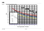
As an example, the charts on the following pages show the maximum rotation speed of the
electrospindle when empty, on the basis of the weight of the TOOL+TOOL HOLDER assembly
(including ring nut and mill collet if present), and of the distance between the nose of the
electrospindle and the centre of gravity “G” of the tool+tool holder assembly.
Next to each chart there is the tool+tool holder assembly that was envisaged as assembled in the
spindle shaft to calculate the curves.
The mass of the tool+tool holder assembly was applied to the centre of gravity “G”, highlighted in
the design.
Some possible positions of the centre of gravity “G” were considered, and for each position a curve
has been drawn on the chart.
The degree of balancing is that recommended in the previous paragraphs.
i
If the position of the centre of gravity “G” is not known, section 6.7.2.1gives a simplified
procedure to calculate it.
6.7.2.1 Calculating the centre of gravity of the tool+tool holder assembly
If the position of the centre of gravity of the tool+tool holder assembly is not indicated by the
manufacturer, it can be roughly calculated in the following way:
1. Consider the tool as made up of elementary parts; in the example of the following figure, the
tool consists of two cylindrical parts (one being a slot) and two truncated conical parts.
x


