background image

4


1002

FA 500.2

Combination with 
HSM KP 80

3 Overview

7

4

3

2

5

  1 

Main switch (only solo-version)

  2


Keypad

  3


Emergency stop button

  4


Loading tray

 5 

Intake 

conveyor,


paper feed opening

  6 

Braking swivel castors

 7 

Nameplate

 8 

Oiler

8

6

1

http://www.monomachines.com/

http://www.monomachines.com/

Summary of Contents for HSM FA 500.2

Page 1: ...HSM FA 500 2 OPERATING INSTRUCTIONS PAPER SHREDDER Keep this instruction for future use 1 655 999 112 1002 english http www monomachines com http www monomachines com ...

Page 2: ...ransportation installation 6 6 Operating and display elements on the keypad 7 7 Start up and inspecting the safety devices 8 8 Malfunctions 10 9 Maintenance and care 10 10 Technical data 13 11 Electric wiring diagrams for Solo and Combination version 14 http www monomachines com http www monomachines com ...

Page 3: ...he operating manual and keep it for later use and to pass on to any subsequent users Do not remove or modify safety devices which guar antee the safe operation of the machine Observe all safety instructions attached to the ma chine Carry out inspection and maintenance regularly Switch off the shredder disconnect the power plug and call customer service in the following circum stances power cables ...

Page 4: ...0 3 Overview 7 4 3 2 5 1 Main switch only solo version 2 Keypad 3 Emergency stop button 4 Loading tray 5 Intake conveyor paper feed opening 6 Braking swivel castors 7 Nameplate 8 Oiler 8 6 1 http www monomachines com http www monomachines com ...

Page 5: ... Combination version HSM FA 500 2 Stand alone version Combination version Stand alone version 2 x 180 kg 2 x 180 kg 1590 1925 max 1410 1185 960 630 500 1155 880 500 880 1155 560 910 960 630 1000 500 1255 3500 1000 500 1255 2590 1410 1185 820 2500 1925 max http www monomachines com http www monomachines com ...

Page 6: ...pproximately 180 kg The machine must be connected to a power source which meets the specifications on the nameplate Make sure the power cable is unobstructed and that nobody can tread on it Mount the loading table onto the unit Remove screws 1 and 2 from the frame Fasten the supports to the frame with the screws 2 Place the table on the supports Make sure the oil hose is not bent Fasten the table ...

Page 7: ...on Stop button The cutting block and feed belt stop The shredder is in standby mode Reverse button The cutting block and feed belt run in reverse Paper jam or overload Red LED Safety circuit interrupted Red LED Solo machine Lock the front castors by pressing down the brake le ver Combination version The assembly of the shredder with the baling press is described in the operator s manual of the Shr...

Page 8: ...verse if the phase wires in the power plug are incorrectly con nected Turn off the main switch immediately and pull out the power plug Have an electrician change two of the three phase wires Checking the emergency stop button Press the emergency stop button while the machine is running The shredder must switch off immedi ately The cutting block and the feed belt must stop The machine will only sta...

Page 9: ...and feed belt start up Place the material to be shredded on the loading tray and then place batches on the feed belt If material that is not supposed to be shred ded is mistakenly placed onto the belt never attempt to pull it out Press the stop button The drive stops Press the reverse button The cutting block and feed belt run in reverse You can now remove the material from the belt and start the ...

Page 10: ...n the keypad lights up The shredder switches off automatically Check Safety flap on the feed belt is closed The dust tray is pushed in completely only stand alone version The inspection door is closed only stand alone version The protective flap is in vertical position Press the green start button 9 Maintenance and care Cleaning the cutting unit if the cutting quality deteriorates or the machine b...

Page 11: ...s flush with the con veyor belt Otherwise it must be readjusted Loosen the countersunk screws of the clamping strip this allows to move the stripping device Align the stripping device and retighten the counter sunk screws If the stripping bar is worn it must be replaced The area below the stripping device should be cleaned at the same time Greasing the drive chains and cogs twice yearly Switch off...

Page 12: ... after long periods of use If you can see the fabric inlay in the belt it must be replaced Please notify our customer service 1 2 3 Cleaning the shredder Switch off the shredder and disconnect the mains plug When cleaning only use a soft cloth and a mild soap water solution Never use scouring agents cleaning fluid petroleum or thinners Cleaning the tensioning station monthly Remove the feeding tab...

Page 13: ...00 2 corresponds to the health and safety requirements of the following EC directives listed below due to its conception and design of the version in which it was put into circulation by us Machinery directive 2006 42 EC EMC directive 2004 108 EC Applied standards and technical specifications EN 349 1993 A1 2008 EN 62061 2005 EN 12100 1 2003 A1 2009 EN 12100 2 2003 A1 2009 EN 55014 1 2006 EN 55014...

Page 14: ...14 1002 FA 500 2 Solo 400 V 11 Electric wiring diagrams Solo 400 V 50 Hz Legend AV Shredder S in switch cabinet MA on machine BF Keypad http www monomachines com http www monomachines com ...

Page 15: ...1002 15 FA 500 2 Solo 400 V http www monomachines com http www monomachines com ...

Page 16: ...16 1002 FA 500 2 Solo 400 V http www monomachines com http www monomachines com ...

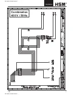
Page 17: ...1002 17 FA 500 2 Kombi 400 V Combination 400 V 50 Hz http www monomachines com http www monomachines com ...

Page 18: ...18 1002 FA 500 2 Kombi 400 V http www monomachines com http www monomachines com ...

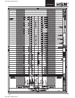
Page 19: ...1002 19 FA 500 2 Kombi 400 V http www monomachines com http www monomachines com ...

Page 20: ...20 1002 FA 500 2 Kombi 400 V http www monomachines com http www monomachines com ...

Reviews: