background image

16  


SP 4040

 11/2012

SP 4040

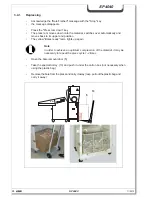
-  Remove the screws from the cover plate on the press hopper -> screws (M6) and store 

in a safe place!

2.5 

Assembling the press and shredder

Danger!

For safety reasons the hopper for the press must remain covered with 
a cover plate until initial operation. Crushing and cutting elements are 
uncovered if the hopper is open . 

The press should only be used in conjunction with a shredder (type FA
400.2).

Do not turn on the main switch of the press before the press and 
the shredder have been screwed together.

Note
For transport reasons the press ram is in the lowest position. The bale 
removal door cannot be opened yet.

Summary of Contents for SP 4040

Page 1: ...2 513 999 220_en SP 4040 OPERATING MANUAL SHREDDER PRESS COMBINATION SP 4040 Keep in a safe place for future use ...

Page 2: ...2 SP 4040 11 2012 SP 4040 HSM GmbH Co KG Austraße 1 9 88699 Frickingen Germany Tel 49 7554 2100 0 Fax 49 7554 2100 160 mailto info hsm eu www hsm eu ...

Page 3: ... 12 2 3 3 Power requirement and fuse rate 13 2 3 4 Noise emission 13 2 3 5 Operating conditions 13 2 3 6 Measurements chart Baling press HSM KP 40 V Shredder FA 400 2 14 2 4 Assembling the shredder 15 2 5 Assembling the press and shredder 16 2 6 Start up 18 3 Operation 19 3 1 Machine overview 19 3 2 Operating and display elements of the baling press 20 3 2 1 Call up the SERVICE menu 23 3 2 2 Adjus...

Page 4: ...ing cutting device 1x daily 36 5 3 2 Checking chain tension 2 x annually FA 400 2 37 5 3 3 Greasing drive chains and cogs 2x annually FA 400 2 38 5 3 4 Tightening the feeding belt FA 400 2 38 5 3 4 1Check that the feeding belt runs straight 39 5 3 4 2Checking the feeding belt for wear 39 6 Disposal instructions 39 6 1 Disposal verifi cation form 40 7 Electrical and hydraulic circuit diagrams 41 7 ...

Page 5: ...symbol indicates particularly important instructions in this manual which must be observed in order to ensure that guidelines and regu lations are correctly adhered to that work is carried out in the proper order and that damage to the machine or other plant compo nents is prevented 1 2 Classification of hazards 1 2 1 Danger Indicates an immediate danger Failure to take heed of this warning will r...

Page 6: ...se charged with installation assembly disassembly start up operation inspec tion maintenance or repair of the shredder press combination must have first read and fully understood the entire operating manual paying particular attention to the Safety section The shredder press combination may only be operated serviced and repaired by au thorised trained staff These staff must have been given special...

Page 7: ...s still running Never open doors and flaps before the machine has been shut down Note the instruc tion plate Test the protective measures installed after any electrical or repair work No platforms or other raised surfaces may be placed near the shredder press combina tion if they encroach on the specified safety clearances Connecting cables must be laid in such a way that they cannot be tripped ov...

Page 8: ...achine is operated continuously After any maintenance or repair work Check that the safety devices Are in the correct condition Are in the correct position Are firmly secured Are working properly If any defects arise during operation stop the machine immediately and ensure that the defect is corrected Do not modify or remove any of the protective devices Do not deactivate any of the pro tective de...

Page 9: ...ing operation The shredder press combi nation and the shredder should switch off immediately It should not be possible to turn on any of the machines as long as the bale removal door is open After the bale re moval door has been shut the Ready lamp on the shredder should light up again 1 If you press the Emergency Stop button 2 on the shredder it should switch off im mediately and the Ready lamp s...

Page 10: ...k the safety switch 3 on the front door If the door is opened then the shredder must switch off immediately and the Door open lamp should light up It should not be possible to turn the shredder on as long as the door is open After the door has been shut the Door open lamp must go off 3 ...

Page 11: ...ints indicated in the diagram should always be used Note that the shredder and the baling press have a high centre of gravity 2 2 Transport 2 1 Operating conditions The machines should only be operated in dry rooms If the temperature is less than 0 C a different hydraulic fluid with a more suitable viscosi ty will be required Place the machines on a smooth level surface Remove the packaging The sh...

Page 12: ...3 2 Shredder FA 400 2 Cutting type Strip cut Cross cut Cut size mm 5 8 5 8 x 50 3 9 x 40 Safety level DIN 66399 P 2 O 2 T 2 E 2 P 3 O 2 T 3 E 2 P 4 O 3 T 4 E 3 F 1 Safety level DIN 32757 1 2 3 3 Cutting capacity sheets DIN A4 70 g m 80 g m 130 104 120 96 95 100 80 85 Cutting speed 210 mm s 220 mm s Effective width 428 mm Weight ca 425 kg Waste container volume Solo machines 1 chamber system 2 cham...

Page 13: ... Fuse 25A K Charakteristik Control voltage 24VDC Guideline EN 60204 Plug electrical connection CEE 32 2 3 4 Noise emission FA 400 2 KP 40 V Idle 61 dB A 69 dB A Loaded 75 dB A 75 dB A 2 3 5 Operating conditions Operating temperature 10 C 40 C Operating humidity max 90 non condensing Operating altitude max 2200 m above sea level ...

Page 14: ...14 SP 4040 11 2012 SP 4040 2 3 6 Measurements chart Baling press HSM KP 40 V Shredder FA 400 2 ...

Page 15: ... and should only be mounted at the installation site FA 400 2 Screw the loading table on the top to the frame using the 2 Phillips screws 1 and at the bottom with 2 nuts 2 each at the left and the right side 1 2 The shredder may only be placed in dry rooms on a firm even floor no carpeting The foot load is approx 107 kg on every roller ...

Page 16: ...t remain covered with a cover plate until initial operation Crushing and cutting elements are uncovered if the hopper is open The press should only be used in conjunction with a shredder type FA 400 2 Do not turn on the main switch of the press before the press and the shredder have been screwed together Note For transport reasons the press ram is in the lowest position The bale removal door canno...

Page 17: ...an be adjusted Fix the shredder s discharge chute firmly onto the input chute of the press with the 4 screws M6 Lock the brake pedals on the casters of the shredder and press Plug the mains plug H of the shredder into the socket on the control cabinet of the press Plug the mains plug of the press CEE plug into a socket at the installation site which must be protected by a slow 32 A fuse H ...

Page 18: ...en the press ram automatically moves to top end limit position without any button being pressed Turn the main switch on the press on The press ram moves to the top end limit and afterwards the press switches off auto matically It is now possible to open the bale removal door Open the bale removal door Fold out a carton box in the correct manner l x w x h 590 x 390 x 485 mm no 6111995101 and glue t...

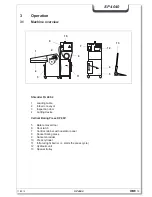
Page 19: ...ith operator panel 8 Socket baling press 9 Socket shredder 10 Press cylinder 11 Infrared light barrier starts the press cycle 12 Hydraulic unit 13 Special trolley Shredder FA 400 2 1 Loading table 2 Infeed conveyor 3 Inspection door 4 Cutting device 3 1 Machine overview 13 FA 400 HSM KP 40 V 0 8 9 3 6 5 1 2 10 11 7 4 12 ...

Page 20: ...the baling press 1 Main switch 2 Automatic 3 Automatic light symbol 4 Standby Ready for operation 5 Raise press ram 6 Press ram stop 7 Lower press ram 8 Bale finished 9 Malfunction 10 Menu selection scroll up down 11 Display SERVICE ELECTRONIC 11 2 8 4 10 9 6 7 3 5 1 ...

Page 21: ...er Screen display Manual operation in starting position The light symbol is flashing as long as the door of the baling press is open Screen display Manual operation Door Loading flap open The light symbol is flashing in set up mode resp at the message Bale finished Raise press ram soft key 5 When this soft key is pressed the press ram returns into its upper end position with the door closed Screen...

Page 22: ...on is reached the motor of the press is switched off The Bale finished message goes off when the door is opened Light symbol Malfunction 9 This message is displayed when there is any malfunction on the combination press Combi nation press and paper shredder are switched off and a malfunction number appears on the screen see section Malfunctions Screen display 11 On the display are shown the runnin...

Page 23: ...2 By simultaneous pressing of the keys again for approx 3 seconds you come to the corresponding adjustments resp displays The selection is acknowledged with the or key Changed adjustments must be acknowledged by simultaneous pressing the keys SERVICE 3 sec Menu SERVICE 3 sec Adjustments Display User language D GB F Set up mode Set up mode yes no Compression time Compression time xxx Bale counter N...

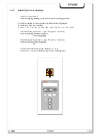
Page 24: ...ent user languages The following ones are available D GB F E I P NL S FIN DK GR TR PL CZ HU RUS Simultaneously press the keys for approx 3 seconds Screen display Selection with User language Simultaneously press the keys for approx 3 seconds Screen display User language D Scroll to the desired language using the keys Press the keys simultaneaously for acknowledgement SERVICE ELECTRONIC ...

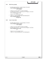
Page 25: ...et up mode no Press the key 1x and jump to yes Press the keys simultaneously for acknowledgement Screen display Attention Set up mode 3 2 4 Leave set up mode Simultaneously press the keys for approx 3 seconds Screen display Selection with User language Press the key 2x until Set up mode is displayed Simultaneously press the keys once more for approx 3 seconds Screen display Set up mode no Press th...

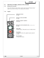
Page 26: ...en This switches off the shredder 3 3 2 Keypad Safety flap not shut Red light Overfeed motor overloaded Red light Apparatus ready for operation Green light Baling Press not in automatic mode corresponds bag full indicator Red light Start button Apparatus starts cutting device moves in intake direction Stop button Cutting device stands still apparatus remains ready for operation Reverse button Cutt...

Page 27: ...from the conveyor belt and the shredder can be started again with the start key The shredded material falls through the discharge chute of the shredder directly into the carton box inside the press The press cycle is initiated by the infrared light barrier when the carton box has been filled to a certain level The press ram moves downwards presses the material into the carton box alternatively int...

Page 28: ... moves back to its upper end position The yellow Bales ready lamp lights up again Note In order to achieve an optimum compression of the material it may be necessary to repeat the press cycle 1 2 times FA 400 Open the bale removal door 5 Take the special trolley 13 and push it under the carton box not necessary when using the plastic bag Removethebalefromthepressandcarryitaway resp pullouttheplast...

Page 29: ... instead of the carton box see chapter Start up Fold the 4 carton flaps down net on the outside Note If the left carton flap is not bent down correctly the press ram continues moving up and down insert the carton box correctly Put the carton box on the base of the press Close the bale removal door and lock it The press and the shredder are now ready for operation again ...

Page 30: ...hredder combination shutdown Press the Stop key on the shredder Turn the main switch on the shredder off Secure the main switch with a padlock to prevent unauthorised use 3 5 1 Lowering the press ram Move the press ram downwards Press the Stop key on the press when the ram meets counter pressure As long as the press ram is in its bottom end limit position the bale removal door cannot be opened ...

Page 31: ...hredder runs forward Take care that any further loads are made up of rather less paper Frequent overloading The electric motor overheats The red LED on the keypad lights up The shredder switches off automatically Allow the shredder s electric motor around 20 30 minutes to cool down and afterwards start the equipment again Note Load the shredder in equal amounts that fall within the shredder s perf...

Page 32: ...tion Elimination 0100 Phase is missing Electrician Check onsite fuses 0101 Incorrect connection of phases Wrong direct of rotation Electrician Check rotatory field 0110 Oil temperature too high Let oil cool down 0111 Sensing device for oiltemperature defective Electrician Change sensing device 0120 Motor protective relay has swapped Let motor cool down 0121 Emergency off is actuated Pull out emerg...

Page 33: ...Since operating conditions may vary it is impossible to specify in advance how often wear check inspections maintenance and repairs will be necessary A suitable inspec tion routine should be devised according to your particular operating conditions Our customer service experts will be glad to assist you with additional advice Maintenance work may only be carried out by our specialist engineers or ...

Page 34: ... safety cover 16 Unscrew the ventilation filter lid 12 1 The fluid level can be read on the fluid level measuring stick on the ventilation filter lid The fluid level should be in between the two notches on the measuring stick If there is insufficient fluid in the tank pour more fluid into the opening for the ventilation filter lid Change the oil annually to increase the longevity of the hydraulic ...

Page 35: ...ade oil DIN 51524 T3 ISO viscosity grade HVLP 22 Turn on the main switch Move the press ram up and down several times and check the fluid again as de scribed above with the press ram in its topmost position Fill more oil if required Unscrew the ventilation filter lid again Mount the safety cover onto the unit again Note Observe the applicable accident prevention regulations when handling cleaning ...

Page 36: ...o 1 235 997 500 for 5 l tank Let the cutting device run forwards and backwards several times without feeding in any paper This loosens paper dust and particles Cross cut machines If the cutting quality detoriates or hte machine becomes noisy Let the shredder run without feeding any paper Push the lever of the oiler down several times Make sure that the oil level in the container is between the MIN...

Page 37: ...10 mm Tighten the nuts again Mount the cover plate and the loading table onto the unit again Note Do not tighten the chain too much as this will wear the chain and the bearings faster than would otherwise be the case The chain sag should be 4 10 mm 5 3 2 Checking chain tension 2 x annually FA 400 2 Switch off the shredder at the main switch Pull out the mains plug Remove the tray and the cover pla...

Page 38: ...umverseift Bearing grease lithium saponified Aralub HL 3 Energrease LS 3 Glissando 30 Exxon BEACON 2 Mobilux EP 2 ALVANIA Fett R 3 SHELL 5 3 4 Tightening the feeding belt FA 400 2 The feeding belt should not slip when loaded with material Switch off the shredder and pull out the mains plug Loosen the hexagonal nuts 1 on the left and on the right side of the snub roller Loosen the lock nuts 2 of th...

Page 39: ...evertheless every machine reaches a time when inspections and repairs are no longer worth the trouble The opera tor then faces the problem of disposing of the machine properly We will be glad to advise you about the legal regulations for disposal at the appropriate time The baling press and shredder are made of different materials and need to be disassem bled to separate the materials for recyclin...

Page 40: ...ress Shredder Model ______________________________ Machine number ______________________________ Year of construction ______________________________ has been disposed of according the applicable regulations Address of the last operating company Address of the waste management company Date and signature Date and signature of the last operator of the disposal company ...

Page 41: ... Frickingen Telefon 49 7554 2100 0 Telefax 49 7554 2100 160 The machine number is stated on the nameplate on the shredder resp the baling press It is difficult to deal with warranty claims and queries unless you quote the machine num ber HSM GmbH Co KG Austraße 1 9 88699 Frickingen Germany Schnittbreite Baujahr Spannung Leistung Nennstrom Masch Nr Modell Made in Germany Seriennummer 7 1 Electrical...

Page 42: ...42 SP 4040 11 2012 SP 4040 7 2 Hydraulic diagrams ...

Page 43: ...1000 6 4 01 07 EN 61000 6 2 03 06 The individual operation of the machines is prohibited Only the combination of the shredder and the baling press complies with EN 13857 safety distances Frickingen 24 03 2010 p p Hubert Kötzinger Head of Environmental Engineering Product Development Authorised representative for the compilation of technical documentation Hubert Kötzinger HSM GmbH Co KG The technic...

Reviews: