HLogic Security Technology Co., Ltd
www. hstfire .com
Document Ref: M7285-01
Issue:1.0
07/2016
INSTALLATION AND MAINTENANCE INSTRUCTIONS
HS201
Addressable Sounder Strobe
Notice:
This manual should be left with the owner/user of this equipment.
General Description
The sounder strobe remains the most commonly used alarm for fire evacuation system, for wall or
ceiling applications, indoors.
The sounder strobe is intended for use in addressable, two-wire systems where the individual
address of each device is written inside the MCU’s EEPROM by the addressable programmer.
Wiring
The system designer must make sure that the total current drawn by the devices on the loop does
not exceed the current capability of the panel supply, and that the last device on the circuit is
operated within its rated voltage.
When calculating the voltage available to the last device, it is necessary to consider the voltage
drop due to the resistance of the wire. The thicker the wire, the smaller the voltage drops. Wire
resistance tables can be obtained from electrical handbooks.
Specifications
Loop Voltage:
16 to 28VDC
Standby Current:
450uA@28VDC
(
Maximum in loop
)
Alarm Current:
7mA (With LED latched on in loop)
External power supply:
16 to 32VDC
External supply standby current: 4mA@28VDC(Maximum)
External supply alarm current:
35mA@28VDC(Maximum)
Sound level:
80dB(A)/1m(Minimum)
Standard:
EN54-3&23
Strobe signal strength:
75cd
Flash rate:
1 Flash Per second
Operating Temp:
-10
℃
to +50
℃
Operating Humidity Range:
10% to 93% Relative Humidity, Non-condensing
Dimensions:
87 mm L x 87mm W x 47mm H
Weight:
106g
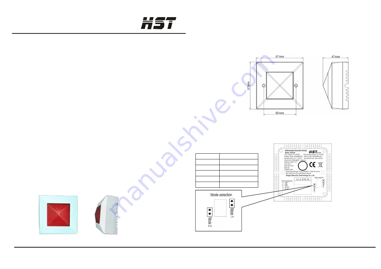
Figure 1
Addressable sounder strobe
Installation Wiring
Before Installing
This information is included as a quick reference installation guide. Refer to the control panel
installation manual for detailed system information. If the sounder strobes will be installed in an
existing operational system, inform the operator and local authority that the system will be
temporarily out of service. Disconnect power to the control panel before installing the sounder
strobes.
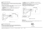
Installation Dimensions
Figure 2
Dimensions of sounder strobe
Terminal Details
Terminal
Description
L+
Loop+
E
Earth
L-
Loop-
V+
External power+
V-
External power-
Figure3
Terminal and configuration of sounder strobe
Mode 1
: 2 wires of loop, do not need connect to external
Power supply, it has sounder function only without strobe.
Mode 2
: 4 wires, 2 wires of loop,2 wires of external power
Supply, have sounder and strobe functions (
default
);
©


