background image

“SMART Plus”


Electronic control for towel radiators


Rev. 02 – April 2015


SI


NO


10) 

When the level of the liquid stops growing wait for additiona 
5 minutes then stop heating.


11) 

If necessary, top up the radiator before the liquid cools dow 
(keep the temperature of the internal liquid under control).


12) 

Close the top opening of the radiator with the appropriate 
cap.


13) 

Hook the radiator to the wall.


14) 

Connect the device to the mains


(4)


(3)


(1)


(2)


Installation guide


For authorized installer only


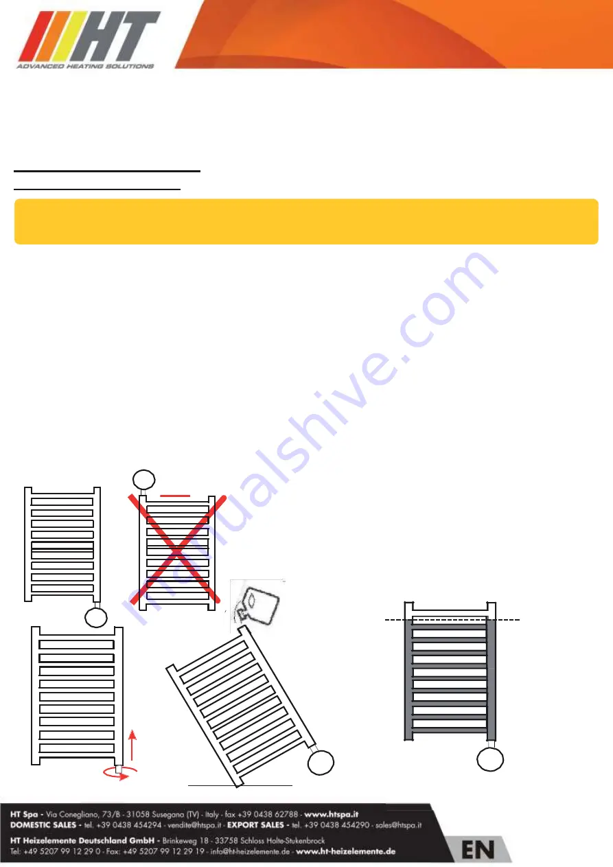
1)  Insert the heating element in the threaded opening located on the bottom part of the radiator.


2)  Securely fasten the electric resistance to the body of the towel radiator with a 22mm  wrench.


3)  The special sheath ensures a secure mounting and eventually allows a slight supplemental torsion to perfectly 

align the thermostat with the radiator.


4)  Tilt the radiator as in fig. 3, making sure that the opening on top of the radiator is located on the highest side. 

WARNING. Do not lean the radiator on the electronic control!


5)  Fill the radiator with the specific liquid.


6)  Put the radiator back in vertical position and check the internal level of the liquid (fig. 4).


7)  Ensure a proper fastening of the heating element in the radiator.


8)  Connect the device to mains and start heating (the top opening of the radiator must remain open!).


9)  Set the maximal temperature and check the level of the internal liquid.


- Due to thermal expansion the liquid could brim over the radiator. 

Remove the exceeding liquid (do it with care to avoid burns!) in order to keep the thermostat dry 

and avoid the liquid reaching the border


• 

Disconnect the device from power supply before proceeding with installation..


• 

Protect the device with a 30mA RCD circuit breaker

.


Rev.3 agosto 2020 

Summary of Contents for SMART Plus

Page 1: ...d temperature The temperature is however automatically controlled in order not to exceed 29 C At the end of the 2 hours period the device returns to Comfort mode Timer mode The control system enters into Boost mode for 2 hours after that it returns into Comfort mode for 22 or 10 hours period configurable by the user and then it enters again into Boost mode for 2 hours This sequence is repeated end...

Page 2: ...N 50366 2003 EN 55014 1 2008 EN 55014 2 1998 Approval mark CE Case ABS VO Environmental directive WEEE RoHS Electromagnetic compatibility 89 336 EEC Operative modes Comfort Boost2h Timer12h Timer24h Standby Antifreeze Key lock Thermostat status indicator Boost Timer LED red green amber Comfort Bar with 6 LEDs 1 blue 1 green 2 yellows 2 reds Connection to mains 3 Cables neutral live earth Italian p...

Page 3: ...ating element Any other use is forbidden Before using carefully ensure that the line voltage is the same as that specified for the device see technical specifications Only use heating elements compatible with the type of used towel radiator Disconnect power supply before cleaning or before performing maintenance of theproduct In case of damage of the power supply cable shut down the device and do ...

Page 4: ...ntal torsion to perfectly align the thermostat with the radiator 4 Tilt the radiator as in fig 3 making sure that the opening on top of the radiator is located on the highest side WARNING Do not lean the radiator on the electronic control 5 Fill the radiator with the specific liquid 6 Put the radiator back in vertical position and check the internal level of the liquid fig 4 7 Ensure a proper fast...

Page 5: ...ing on the radiator and buttons For setting the desired temperature Boost Timer Button To select one of Boost Timer12 and Timer24 modes Comfort bar Boost Timer Led Small red green amber light indicator to inform about the active mode Power cord External NTC sensor Used for automatic temperature control 15 5 C 14 C 7 C Blinking LED 18 5 C 17 C 20 C 21 5 C 23 C 24 5 C 26 C 27 5 C 29 C Rev 3 agosto 2...

Page 6: ... blinking LED in the Comfort bar indicates the selected temperature see table and figures below Examples First configurable Comfort temperature 14 C Press once the button The configured temperature is of 18 5 C first yellow LED blinking Press 4 times the button The configured temperature is of 23 C second yellow LED permanently lit Press 7 times the button Antifreeze temperature Standby mode In th...

Page 7: ...of the Comfort mode is of 21 hours Timer24 indication During 2hrs Boost Boost Timer LED blinkinggreen During 22hrs Comfort Boost Timer LED permanent green Timer12 mode Press the Boost Timer button for more than 5 seconds to activate it The control system activates the Boost mode for 2 hours after that it returns into Comfort mode and after 10 hours the Boost mode is started again for 2 hours This ...

Page 8: ...id inadvertent modifications of the settings Press together the and buttons for 3 seconds to lock all the buttons except the On Standby button To unlock the buttons press again together the and buttons buttons for 3 seconds When key lock is activated the device beeps twice When key lock is deactivated the device beeps four times Additional indications provided by the Comfort Bar The two central ye...

Reviews: