7
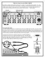
Example One: Connecting the a whole-house audio controller to the amplifier.
Use the Line Outputs on the controller (example shown is the HTD Lync6) to connect to the Line Inputs on the amplifier
channels for each zone. We include six 3’ shielded stereo patch cables with the Lync6 for this purpose.
Amplifier Settings
Two side-by-side amplifier channels are used for each
zone. One side is set to amplify the Right channel of a
stereo signal and the other side is set to amplify the Left
side of a stereo signal. In our diagram, channel 1 is set to
amplify the Right channel and channel 2 is set to amplify
the Left channel for the speakers in Zone 1.
Level:
Turn the rotary Level knob all the way clockwise to get the maximum power out of the ampli-
fier. You can set the Level at less than maximum to limit the volume output in a zone (e.g. limit how
loud a child can play his/her music). See “Best Practices” under Level Settings on Page 4 for more
information.
Input Selection Switch:
Set to “Line”.
L, L+R, R Switch:
When the “Line” input is used, this switch is inactive so the setting is irrelevant.
However, you might want to set odd numbered channels to Left (L) and even channels to Right (R)
just to make it easier to recall which Line Output from the Lync6 is being sent to each channel.
Bridge Switch:
Since you are not bridging the two channels, make sure the Bridge Switch is off (far
left position).
*See WARNING on page 4*
On - Auto On - Trigger Switch: When used with a whole-house audio system,
it is best to set this
switch to “Trigger” which will have the amplifier power on whenever a keypad is turned on, and
return to sleep mode once all keypads are powered off. “Auto On” may not always recognize a
low-level source signal coming from the Lync6, i.e. if a zone’s volume is too low, the amplifier might
not wake up from sleep mode.
On
Auto On T
rigger
H
ow to Connect and Use the DMA-1240/DMA-1275
3’ Shielded Stereo
Patch Cables

