10
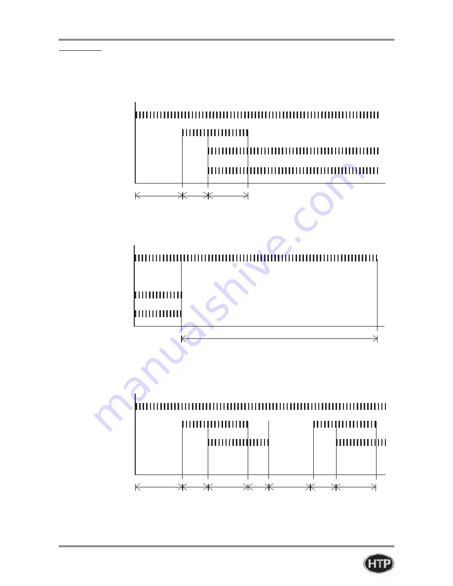
FAN
FAN
FAN
3s 1.5s 3s
120s (1st : 60s + 2nd 60s)
3s 1.5s 3s
1.0s 10s 1.0s 3s
■ If normal ignition
■ If flame extinguishes
■ If abnormal ignition (Alarm after the 10 trial)
IGNITION
IGNITION
IGNITION
GAS VALVE
GAS VALVE
GAS VALVE
FLAME DETECTION
FLAME DETECTION
FLAME DETECTION
Chapter 1 Product Characteristics
■ Time chart
LP-528 REV. 8.01.14
Summary of Contents for EFTC-140F
Page 3: ...1 LP 528 REV 8 01 14 ...
Page 13: ...11 Operation flow chart Chapter 1 Product Characteristics LP 528 REV 8 01 14 ...
Page 14: ...12 Operation flow chart Chapter 1 Product Characteristics LP 528 REV 8 01 14 ...
Page 15: ...13 Wiring Diagram Chapter 1 Product Characteristics LP 528 REV 8 01 14 ...
Page 16: ...14 Wiring Diagram Chapter 1 Product Characteristics Mixing Valve LP 528 REV 8 01 14 ...
Page 42: ...40 Chapter 3 How to use control panel LP 528 REV 8 01 14 ...
Page 67: ...65 Chapter 4 Troubleshooting 1 Flame Detection LP 528 REV 8 01 14 ...
Page 70: ...68 Error code Chapter 4 Troubleshooting LP 528 REV 8 01 14 ...
Page 71: ...69 Chapter 4 Troubleshooting LP 528 REV 8 01 14 ...
Page 72: ...70 Chapter 4 Troubleshooting LP 528 REV 8 01 14 ...
Page 106: ...104 1 Cabinet Replacement Parts Chapter 7 Repair Part Diagram LP 528 REV 8 01 14 ...
Page 107: ...105 Chapter 7 Repair Part Diagram LP 528 REV 8 01 14 ...
Page 108: ...106 2 Combustion System Replacement Parts Chapter 6 Repair Parts Diagram LP 528 REV 8 01 14 ...
Page 109: ...107 Chapter 7 Repair Part Diagram LP 528 REV 8 01 14 ...
Page 110: ...108 Memo LP 528 REV 8 01 14 ...
Page 111: ...109 Memo LP 528 REV 8 01 14 ...
Page 112: ...110 Memo LP 528 REV 8 01 14 ...


