background image

LP-743 Rev. 000 Rel. 000 Date 8.25.20

4

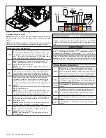
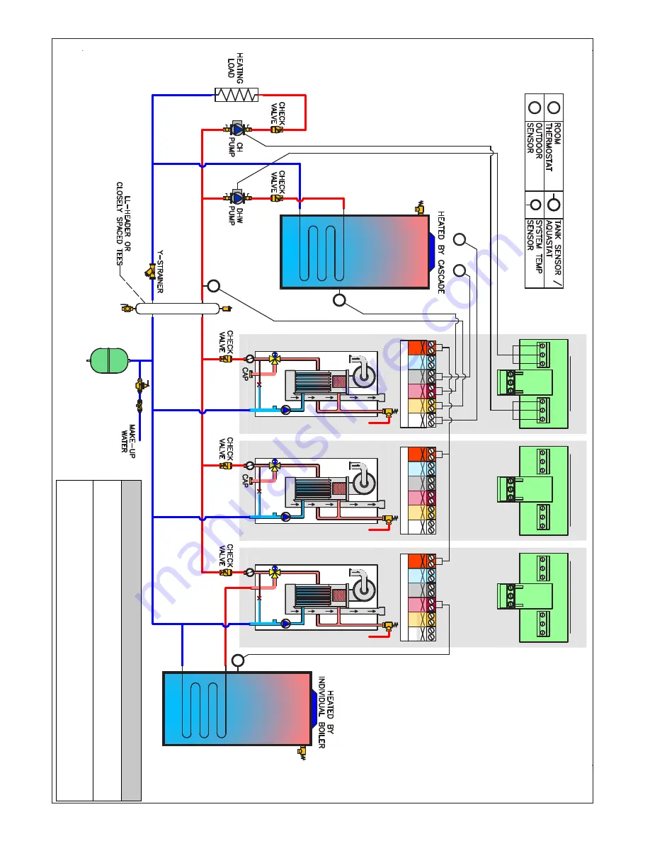
Figur
e 2 - 

Thr

ee (3) C

asc
aded B

oilers with Upstr

eam or Do

wnstr

eam I

ndir
ec

t W

at

er H
ea

ter - P

iping and 

W

iring f

or EL

U-150WBN, EL

U-199WBN, EL

U-199W

CN, and all EFTU mo

dels ONL

Y

S

TS

TS

TS

S

BUS

T   B

120V

TT2

120V

OD

5V  IN

120V

TNK

120V

SYS

120V

TT1

120V

PCB / CONTROL PANEL

BUS

T   B

120V

TT2

120V

OD

5V  IN

120V

TNK

120V

SYS

120V

TT1

120V

PCB / CONTROL PANEL

BUS

T   B

120V

TT2

120V

OD

5V  IN

120V

TNK

120V

SYS

120V

TT1

120V

PCB / CONTROL PANEL

DHW

PUMP

CH

PUMP

120VAC JUNCTION BOX

RT

DHW

PUMP

CH

PUMP

120VAC JUNCTION BOX

RT

OD

OD

MASTER

FOLLOWER

FOLLOWER

DHW

PUMP

CH

PUMP

120VAC JUNCTION BOX

DOWNSTREAM

INDIRECT FIRED

WATER HEATER

UPSTREAM

INDIRECT FIRED

WATER HEATER

Piping f

or M

odels: 

EL

U-150WBN, 199WBN, 199WCN

EFTU-85WBN, 110WBN, 150WBN, 199WBN, 

110WCN, 150WCN, 199WCN

N

O

TICE

In this plumbing applica

tion, par

amet

er 25.1.6 needs t

o be adjust

ed t
o setting 1. 

This ensur

es the CH pump will not oper

ate dur
ing DHW demands

.

Follo
w the Establishing B

oilers as M

ast
er and F

ollo
w

ers instruc

tions when 

connec

ting t

o the BUS t

er

minals

. C

onnec

ting t

o the BUS t

er

minals without 

follo
wing these instruc

tions c

ould damage the main PCB

.

Summary of Contents for EFTU Series

Page 1: ...er birth defects or other reproductive harm The surfaces of these products contacted by potable consumable water contain less than 0 25 lead by weight as required by the Safe Drinking Water Act Section 1417 Heat Exchanger Bears the ASME H Stamp This document is provided in addition to other documentation and DOES NOT REPLACE the installation manual This document must only be used by a qualified in...

Page 2: ...tream of all closely spaced tees 4 The minimum individual boiler pipe size of DHW piping should be diameter and CH piping should be 1 in diameter 5 Circulators are shown with isolation flanges The alternative is standard flanges with full port ball valves Purge valves can be used with circulator flanges as an alternative 6 Piping shown is Primary Secondary 7 Install a minimum of 12 diameters of st...

Page 3: ...NCTION BOX BUS T B 120V TT2 120V OD 5V IN 120V TNK 120V SYS 120V TT1 120V PCB CONTROL PANEL RT DHW PUMP CH PUMP 120VAC JUNCTION BOX OD OD MASTER FOLLOWER RT FOLLOWER DOWNSTREAM INDIRECT FIRED WATER HEATER UPSTREAM INDIRECT FIRED WATER HEATER Piping for Models ELU 85WBN 120WBN 120WCN 150WCN NOTICE In this plumbing application parameter 25 1 6 needs to be adjusted to setting 1 This ensures the CH pu...

Page 4: ...PUMP CH PUMP 120VAC JUNCTION BOX RT DHW PUMP CH PUMP 120VAC JUNCTION BOX RT OD OD MASTER FOLLOWER FOLLOWER DHW PUMP CH PUMP 120VAC JUNCTION BOX DOWNSTREAM INDIRECT FIRED WATER HEATER UPSTREAM INDIRECT FIRED WATER HEATER Piping for Models ELU 150WBN 199WBN 199WCN EFTU 85WBN 110WBN 150WBN 199WBN 110WCN 150WCN 199WCN NOTICE In this plumbing application parameter 25 1 6 needs to be adjusted to setting...

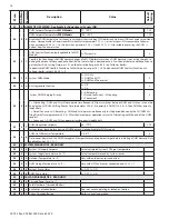
Page 5: ...ishing Boilers as Master and Followers procedure Menu level 25 is not accessible unless 0 4 6 is set to b MAS Parameter Description Value Default Setting 0 4 6 Cascade Boiler Address Master boiler must be set to b MAS UNDEF undefined b SIN single boiler b MAS master boiler b FL1 Follower 1 boiler b FL2 Follower 2 b FL3 Follower 3 b FL4 Follower 4 b FL5 Follower 5 b FL6 Follower 6 b FL7 Follower 7 ...

Page 6: ...er Menu Refer to parameter 5 2 5 and 6 2 5 for CH Zone 2 and 3 4 2 6 Minimum CH Temperature Setting Zone 1 TT1 68 122 F when 4 2 0 0 86 179 F when 4 2 0 1 80 4 2 0 0 120 4 2 0 1 Sets the minimum allowable boiler operating temperature for CH Zone 1 limiting Automatic Temperature Control and manual adjustment from the User Menu Refer to parameter 5 2 6 and 6 2 6 for CH Zones 2 and 3 25 1 6 System CH...

Page 7: ...ting Power 120V for DHW and CH Circulators NOTE TheCHanddownstreamIWHcirculatorsMUSTBECONNECTED to the Master Boiler to ensure proper operation To connect power for the CH and DHW external pump at the boiler junction box 1 Shut off the power supply at the boiler and at the circuit breaker 2 Shut off the gas at the manual shutoff 3 Remove the boiler front cover 4 Disconnect the three clips and open...

Page 8: ... allow Automatic CH Temperature Control or connect Master boiler to WiFi and use Internet Weather TNK Tank Sensor or Aquastat Connect to a tank sensor or Aquastat installed in a Downstream IWH heated by the entire cascade system and set via 25 2 2 Or installed in an Upstream IWH connected to the Master boiler and set via 2 2 8 NOTE The Master boiler cannot heat both a Downstream and an Upstream IW...

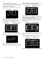
Page 9: ...by Boiler Supply Sensor Master Homescreen 3 Boiler Supply Temperature This screen displays the current temperature read by the master boiler supply sensor 150oF is displayed below Figure 11 Master Homescreen 3 Boiler Off This screen displays if the master boiler is turned off with the ON OFF button Master Homescreen 4 Cascade Master Operating Power Level This screen displays the current operating ...

Page 10: ...iler Operating Power Level This screen displays the current operating power level percentage of the follower boiler A power level of 40 is displayed below PL Denotes Boiler Power Level Current Power Level Percentage Figure 18 Follower Homescreen 3 Boiler Power Level Follower Homescreen 4 Indirect Water Heater Tank Temperature Aquastat Status of Upstream Local IWH This screen is only displayed on t...

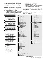
Page 11: ...0 Setpoint 16 Service 1 S W Changeover 17 Error History 2 Z3 Settings 18 Free Parameters 3 Z3 Diagnostics 42 BMS Parameters 7 Z3 Regulation parameters 0 General 8 Service Parameters 1 Analog Level Settings 0 Boiler Statistics 1 2 Diagnostics 1 Boiler Statistics 2 2 Boiler 3 Boiler Temperature 4 Storage 5 Service 6 Error History 7 Free parameters 8 Reset Factory Settings 9 Other 1 10 Other 2 11 HTP...

Page 12: ...ctory Settings 9 Other 1 10 Other 2 11 Boiler Statistics 1 12 Boiler Statistics 2 13 Boiler 14 Boiler Temperature 15 Storage 16 Service 17 Error History 18 Free Parameters 19 20 28 29 31 32 33 34 47 53 Boiler Temperature Quick Access Menus PCB Direct Access to the Parameters 34 40 19 34 40 20 34 40 28 34 40 29 34 40 31 34 34 40 47 34 40 53 ERR Fault The display shows the last 10 errors with the co...

Page 13: ...void short cycling ensure 25 0 4 is set to less than half of 25 0 5 setting Applicable only when parameter 25 0 2 0 25 0 5 Cascade Manager Max Turnover Level par 25 0 4 100 70 Sets the power level threshold where the next boiler is switched on Switches on if required power is 25 0 5 Switches off if required power is 25 0 5 25 0 3 Off logic only applicable if parameter 25 0 2 1 25 0 7 CH On Differe...

Page 14: ... and CH will not operate simultaneously Priority switches between DHW and CH at an interval de fined by the CH DHW Shifting Priority Time parameter 25 0 8 first priority is DHW If 25 0 8 0 then DHW has priority indefinitely 1 Timed Concurrent Alternating DHW and CH operate simultaneously for the period defined by the CH DHW Shi fting Priority Time parameter 25 0 8 After the time elapses operation ...

Page 15: ...LER 1 7 34 40 0 GENERAL 34 40 0 1 DHW Preheating 0 Disabled 1 Enabled 1 Enables disables DHW Comfort Function on WCN models not applicable to WBN models See par 25 2 1 34 40 1 FREE PARAMETER 34 40 1 9 DHW Flow Detection Device Type 0 Flow Switch 1 Flow Meter Varies Default 0 for TRX085 120 110C 150C Default 1 for TRX150 199 199C FTVN085 110 150 199 110C 150C 199C WCN models use a flow meter Not ap...

Page 16: ...ring 34 40 5 3 DHW Switch Off Logic 0 anti scale stop at 144 F 1 7 F setting 0 34 40 5 4 DHW Post Purge and Pump Cycle 0 OFF 1 ON 1 OFF 30secondpost circulationand2minutepost ventilation or3minutepost circulationand5minutepost ventilation if the boiler temperature requires it ON When setting is ON time for post circulation is 3 minutes while the time for post ventilation is 5 minutes Default 0 for...

Page 17: ...40 10 OTHERS 2 34 40 10 0 NOT USED 34 40 10 1 DHW Modulation Setpoint 68 179oF 179 Boiler target temperature during a DHW demand Not applicable for WCN models 34 40 10 2 DHW On Differential Temperature 0 36oF 0 Determines how much the DHW storage tank temperature can drop below target before initiating a DHW demand Only applicable when 2 2 8 1 34 40 10 3 Emergency Setpoint 68 179oF 113 Sets Follow...

Page 18: ...xt maintenance 0 60 months 12 If enabled 8 5 1 1 a notification is made on the display and via the Tele diagnostic Service if applicable warning that it is time for maintenance 34 40 55 1 Enable Maintenance Warning 0 OFF 1 ON 0 34 40 55 2 Maintenance Warning Reset Reset OK Yes Esc No Resets Maintenance Advice and clears the Warning 34 40 55 4 SW Version Display Interface 34 40 55 5 SW Version Main...

Page 19: ...address Press OK again 2 If above process does not work access parameter 0 4 6 and set the correct boiler address see Cascade Control Set Up Blocking Auto Reset EMERG Emergency Mode 1 The Follower has been disconnected from the BUS or no longer sees the Master on the BUS check the BUS connections See Wiring a Cascade System 2 The control has sensed a short circuit on the BUS connection Disconnect ...

Page 20: ...LP 743 Rev 000 Rel 000 Date 8 25 20 20 Maintenance Notes ...

Reviews: