LP-743 Rev. 000 Rel. 000 Date 8.25.20
9
Part 4 - Cascade Controls
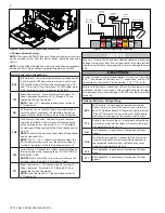
Figure 8 - Master Homescreen 1 - Overall System Detail
MAS Denotes
Master Boiler
Denotes a Three (3)
Boiler System
Flame Detected
with Power Level
A. Master Boiler Homescreen Overview
When viewing the Cascade Master Homescreen, the following screens
will appear on the display and alternate every three (3) seconds.
Master Homescreen 1 - Overall System Details
This screen signifies that this is a master boiler with two (2) followers:
A three (3) boiler cascade system. The CASCADE text below further
lets the user know that this is a cascade system. The system is cur-
rently meeting a CH Zone 1 demand. The bars to the left and right of
the screen detail how close the DHW and CH temperatures are to the
setpoint.
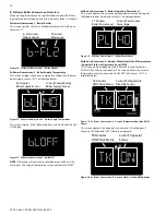
Figure 9 - Master Homescreen 2 - System Temperature
SY Denotes
System Sensor
Current Temp Read
by System Sensor
Master Homescreen 2 - System Temperature
This screen displays the current temperature read by the cascade
System NTC Sensor. 138
o
F is displayed below.
Figure 10 - Master Homescreen 3 - Boiler Supply Temperature
bL Denotes Boiler
Supply Sensor
Current Temp Read by
Boiler Supply Sensor
Master Homescreen 3 - Boiler Supply Temperature
This screen displays the current temperature read by the master
boiler supply sensor. 150
o
F is displayed below.
Figure 11 - Master Homescreen 3 - Boiler Off
This screen displays if the master boiler is turned off with the ON/
OFF button.
Master Homescreen 4 - Cascade Master Operating Power Level
This screen displays the current operating power level percentage
of the cascade master. A power level of 50% is displayed below.
Figure 12 - Master Homescreen 4 - Cascade Master Power Level
PL Denotes Boiler
Power Level
Current Cascade Master
Power Level Percentage
Master Homescreen 5 - Current Indirect Water Heater Tank
Temperature / Aquastat Status (of Downstream/System IWH)
This screen displays the current temperature read by a connected
DHW NTC Tank Sensor. 120
o
F is displayed below.
Figure 13 - Master Homescreen 5 - Current Temperature Read by DHW
Sensor
TK Denotes
DHW Tank Status
Current Temperature
Read by Sensor
This screen displays if an aquastat is connected. ON will appear if
there is a DHW demand; OFF if there is no demand.
Figure 14 - Master Homescreen 5 - Current Status of the DHW Aquastat
TK Denotes
DHW Tank Status
Current Aquastat
Status
NOTE:
The screen will continue to rotate between the five (5) ho-
mescreens. The Supply Temperature screen will indicate “blOFF”.


