56
D. LINE VOLTAGE WIRING FOR
STANDARD BOILER
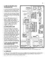
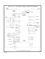
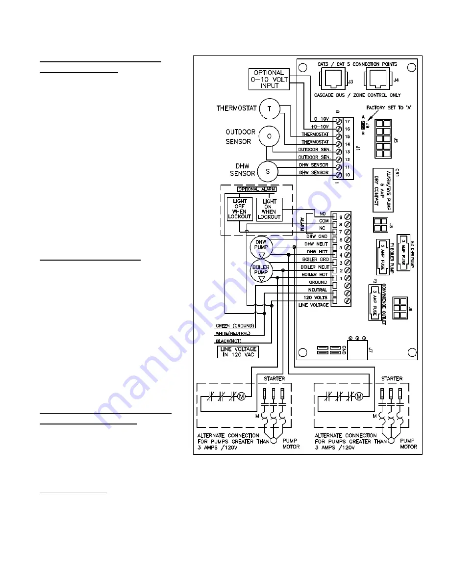
1. Connect 120V / 60Hz / 15 AMP incoming
power wiring to the line voltage terminal strip
in the electrical junction box at terminals
120V, Neutral, Ground (shown in Figure 26).
2. A line voltage fused disconnect or service
switch may be required, externally mounted
and connected according to local codes that
may apply.
3. Connect the boiler pump as shown in
Figure 26 to the terminals marked 4
–
(HOT), 5
– (NEUT), and 6 – (GND). The
connections shown are suitable for a
maximum continuous pump draw of 3 amps
at 120 volts. If the pump requires more
current or voltage than the 120 volts
supplied, an external motor starter or
contactor will be required.
E. ALARM CONNECTIONS
The control includes a dry contact alarm
output. This is an SPDT circuit, rated at 5
amps at 120 volts. This contact can be used
to activate an alarm light or bell or notify a
building management system if the boiler
goes into a lockout condition. The circuit
between the ALARM COM and NC terminals
is closed during normal operation and the
circuit between ALARM COM and NO is
open during normal operation. The
connections depicted in Figure 26 show two
120 volt lights connected to the alarm
terminals. One light will be on when the
boiler is in normal mode and the other light
will be on when the boiler is in lockout mode.
F. LOW VOLTAGE CONNECTIONS
FOR STANDARD BOILER
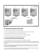
1. All low voltage cables should enter the
electrical junction box through the provided
knock out holes as shown in Figure 25.
2. Connect all low voltage field devices to the low voltage terminal strip located in the electrical junction box.
G. THERMOSTAT
1. Connect the room thermostat to the terminals marked THERMOSTAT in the electrical junction box (see Figure
26). Alternately, any dry contact closure across these terminals will cause the boiler to run. Take caution to
ensure neither of the terminals becomes connected to ground.
Figure 26
– LP-293-NN Elite Boiler Control
Summary of Contents for EL-110
Page 15: ...15 Figure 3 ...
Page 61: ...61 Figure 29 ...
Page 62: ...62 Figure 30 ...
Page 87: ...87 Figure 33 ...
Page 88: ...88 Figure 34 ...
Page 89: ...89 Figure 35 LP 293 A NOTE Parts listed on the following page ...
Page 94: ...94 ...
Page 95: ...95 ...
Page 96: ...96 MAINTENANCE NOTES ...


