77
Press the
▼ key once.
CASCADE SYST 118
o
F
CASCADE SET 190
o
F
This screen shows the current system temperature sensor reading on the top line and the cascade
system temperature setting on the bottom.
Press the
▼ key once.
BOILER 0 100%
BOILER 1 56%
This screen shows the current cascade power demand output on a per connected boiler basis for
boilers addressed as 0 and 1. In the screen above, boiler 0 is being commanded to fire at 100% and
boiler 1 at 56%. If this were a 2 boiler
system, the ‘CASCADE PWR’ screen above would read 156%.
Press the
▼ key once.
BOILER 2 0%
BOILER 3 0%
This screen shows the current cascade power demand output on a per connected boiler basis for
boilers addressed as 2 and 3.
Press the
▼ key once.
BOILER 4 0%
BOILER 5 0%
This screen shows the current cascade power demand output on a per connected boiler basis for
boilers addressed as 4 and 5.
Press the
▼ key once.
BOILER 6 0%
BOILER 7 0%
This screen shows the current cascade power demand output on a per connected boiler basis for
boilers addressed as 6 and 7.
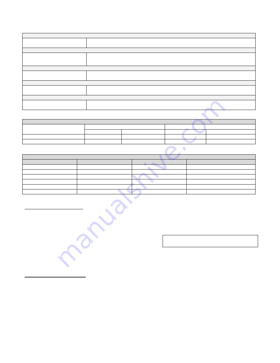
Table 23
– Cascade Menu Screens
COMBUSTION SETTINGS ON ALL MODELS
NATURAL GAS
PROPANE LP
Low
High
Low
High
CARBON MONOXIDE (CO%)
0
– 20 ppm
70
– 135 ppm
0
– 20 ppm
80
– 150 ppm
CARBON DIOXIDE (CO
2
%)
8 ½% - 9 ½%
8 ½% - 9 ½%
9 ½% - 10 ½%
9 ½% - 10 ½%
Table 24
ELITE FAN SPEEDS
MODEL
IGNITION
MIN
MAX
80
3000
1700
4600
110
3800
1700
4950
150
3800
1700
5200
220
3000
1450
4900
299
3000
1450
5000
399
3000
1600
6650
Table 25
D. TEST MODE ACCESS
To activate the test mode, be sure the appropriate pumps are running, then press the
▲ and
ENTER
keys
together for 1 second. The boiler will go through the ignition sequence. Then the user can adjust the fan speed by
pressing
▲ to increase or ▼ to decrease fan speed.
To leave service m
ode, press the ▲ and ▼ keys simultaneously.
PART 11 – TROUBLESHOOTING
A. BOILER ERROR CODE
If any of the sensors detect an abnormal condition, or an internal component fails during the operation of the
boiler, the display may show an error message and error code. This message and code may be the result of a
temporary condition, in which case the display will revert to its normal readout when the condition is corrected, or
it may be a condition that the controller has evaluated as not safe to restart the boiler. In this case, the boiler
control will be locked out, the red FAULT light will be lit, and the mes
sage “LOCKOUT” will be displayed on the
readout on the lower line.
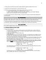
SERVICE RUN
3400 RPM
PUMP ON
4:49P
Summary of Contents for EL-110
Page 15: ...15 Figure 3 ...
Page 61: ...61 Figure 29 ...
Page 62: ...62 Figure 30 ...
Page 87: ...87 Figure 33 ...
Page 88: ...88 Figure 34 ...
Page 89: ...89 Figure 35 LP 293 A NOTE Parts listed on the following page ...
Page 94: ...94 ...
Page 95: ...95 ...
Page 96: ...96 MAINTENANCE NOTES ...

