background image

lp-790 Revision Date 1.3.22

8

To avoid water damage or scalding due to relief valve operation:

• 

Discharge line must be connected to relief valve outlet and 

run to a safe place of disposal. Terminate the discharge line 

in a manner that will prevent possibility of severe burns or 

property damage should the relief valve discharge.

• 

Discharge line must be as short as possible and the same 

size as the valve discharge connection throughout its 

entire length.

• 

Discharge line must pitch downward from the valve 

and terminate at least 6” above the floor drain, making 

discharge clearly visible.

• 

The discharge line shall terminate plain, not threaded, with 

a material serviceable for temperatures of 375

o

F or greater.

• 

Do not pipe discharge to any location where freezing could 

occur.

• 

No valve may be installed between the relief valve and 

heater or in the discharge line. Do not plug or place any 

obstruction in the discharge line.

• 

Test the operation of the relief valve after filling and 

pressurizing the system by lifting the lever. Make sure the 

valve discharges freely. If the valve fails to operate correctly, 

immediately replace with a new properly rated relief valve.

• 

Test T&P valve at least once annually to ensure the waterway 

is clear. If valve does not operate, turn the heater “off” and 

call a plumber immediately.

• 

Take care whenever operating relief valve to avoid scalding 

injury or property damage.

FAILURE TO COMPLY WITH THESE GUIDELINES COULD RESULT IN 

FAILURE OF RELIEF VALVE OPERATION, RESULTING IN POSSIBILITY 

OF SUBSTANTIAL PROPERTY DAMAGE, SEVERE PERSONAL INJURY, 

OR DEATH.

RE-INSPECTION OF T&P RELIEF VALVES: T&P valves should be 

inspected AT LEAST ONCE EVERY THREE YEARS, and replaced if 

necessary,

 by a licensed plumbing contractor or qualified service 

technician to ensure that the product has not been affected by 

corrosive water conditions and to ensure that the valve and 

discharge line have not been altered or tampered with illegally. 

Certain naturally occuring conditions may corrode the valve and 

its components over time, rendering the valve inoperative. Such 

conditions can only be detected if the valve and its components 

are physically removed and inspected. 

Do not attempt to 

conduct an inspection on your own.

 Contact your plumbing 

contractor for a re-inspection to assure continued safety.

FAILURE TO RE-INSPECT THE T&P VALVE AS DIRECTED COULD 

RESULT IN UNSAFE TEMPERATURE AND/OR PRESSURE BUILD-

UP WHICH CAN RESULT IN PROPERTY DAMAGE, SERIOUS 

PERSONAL INJURY, OR DEATH.

Do not thread a cap or plug into the relief valve or block relief 

valve outlet line under any circumstances! Explosion and property 

damage, serious injury, or death may result.

C. Condensation

Condensation can form on the water heater when it is first filled with 

water, and may also occur with a heavy water draw and very cold inlet 

water temperature. This condition is not unusual and will disappear 

as the water becomes heated. However, if the condensation should 

continue, examine the piping and fittings for possible leaks.

Other methods of controlling thermal expansion are available. 

Check 

with the local water utility to determine if a check valve exists in 

the cold water inlet line.

 Contact your installing contractor, water 

supplier, or plumbing inspector for additional information regarding 

thermal expansion.

D. Insulation Blankets

If local codes require external application of insulation blanket 

kits, the manufacturer’s instructions included with the kit must be 

carefully followed.

In addition, pay careful attention to the following so as not to restrict 

the proper function and operation of the water heater:

• 

Do not cover the operating or warning labels attached to the 

water heater or attempt to locate them on the exterior of the 

insulation blanket.

• 

Do not apply insulation to the top of the water heater. This 

could interfere with the safe operation of the electrical 

junction box.

• 

Do not cover the jacket access panel(s) to the thermostat(s) 

and heating element(s) or T&P valve.

• 

Inspect the insulation blanket frequently.

Failure to follow these instructions could result in property damage, 

severe personal injury, or death.

E. Temperature and Pressure Relief Valve

For protection against excessive pressures and temperatures in this 

water heater, ensure temperature and pressure protective equipment 

is installed as required by local codes, but not less than a  combination 

T&P valve meeting the requirements for 

Relief Valves and Automatic 

Gas Shutoff Devices for Hot Water Supply Systems, ANSI Z21.22B / CSA 

4.4-M99

 by a nationally recognized testing laboratory that maintains 

periodic inspection of production listed equipment and materials. This 

valve must be marked with a maximum set pressure not to exceed the 

marked maximum working pressure of the water heater.
The water heater ships with an installed T&P valve. DO NOT OPERATE 

THE WATER HEATER WITH THE T&P VALVE BLOCKED OR REMOVED! The 

T&P valve must be plumbed down so discharge can exit at least 6” 

above the structural floor. The relief line cannot be in contact with any 

live electrical parts.

Summary of Contents for Everlast Elevate ELV055C2X055N

Page 1: ...held liable for typographical errors in literature NOTE TO CONSUMER PLEASE KEEP ALL INSTRUCTIONS FOR FUTURE REFERENCE 272 Duchaine Blvd New Bedford MA 02745 www htproducts com lp 790 Revision Date 1 3 22 The surfaces of these products contacted by potable consumable water contain less than 0 25 lead by weight as required by the Safe Drinking Water Act Section 1417 Use and Care Manual California Pr...

Page 2: ...ls 3 Install or locate this water heater only in accordance with the provided installation instructions 4 Use this water heater only for its intended use as described in this manual 5 Do not operate this water heater if it has been damaged or dropped 8 This water heater should be serviced only by qualified service personnel Contact the water heater installer or a qualified service agency for exami...

Page 3: ...ent and ECO Reset 11 C Adjusting the Tank Booster 12 D Heating Element Replacement Procedure 12 Part 7 Maintenance 14 Part 8 Troubleshooting 16 Part 9 Replacement Parts 17 Limited Warranty 18 Customer Installation Record Form 20 Do not use this water heater for anything other than its intended purpose as described in this manual Doing so could result in property damage and WILL VOID product warran...

Page 4: ...n 32oF 0oC and lower than 104oF 40oC Avoid continuously high levels of humidity Never close existing ventilation openings NOTE When installing in a zero clearance location it may not be possible to read or view some product labeling It is recommended to make note of the water heater model and serial number NOTE A combustible door or removable panel is acceptable front clearance Theservicelifeofthe...

Page 5: ...er treatment is recommended and additional more frequent maintenance may be required If you suspect that your water is contaminated in any way discontinue use of the appliance and contact an authorized technician or licensed professional Failure of electric elements due to lime scale build up on the heating surface low pH or other imbalance IS NOT covered by the warranty Water pH between 6 5 and 8...

Page 6: ...d Temp Max Del Temp Min Del Temp Max Del Temp High Temp Limit ELV055C2X055N 55 6 3 4 41 1 2 51 58 23 1 4 8 3 4 NPT 150 90oF 32 C 130o F 54 C 125oF 51 7 C 170o F 76 7 C 190o F 87 8 C Table 2 Specifications and Dimensions See Table 3 for Electrical Specifications Model Safety Listing Elements and Thermostats Available Wattage Voltage Full Load Current in Amps Single Phase ELV055C2X055N UL 174 2 5 50...

Page 7: ...elief valve causing it to operate during each heating cycle resulting in discharge from theT P This rapid and repeated expansion and contraction of components in the system can cause premature failure of system components including the relief valve and possibly the water heater Replacing the relief valve will not correct thermal expansion A potable hot water expansion tank is required to offset th...

Page 8: ...LT IN PROPERTY DAMAGE SERIOUS PERSONAL INJURY OR DEATH Do not thread a cap or plug into the relief valve or block relief valve outlet line under any circumstances Explosion and property damage serious injury or death may result C Condensation Condensation can form on the water heater when it is first filled with water and may also occur with a heavy water draw and very cold inlet water temperature...

Page 9: ...ler water to clear the system Follow the instructions in this manual if thermostat or mixing valve need adjustment Failure follow these instructions could result in property damage severe personal injury or death due to scalds Make certain that the drain valve is completely closed Open the shut off valve in the cold water supply line Open the hot water faucets to allow air to vent from the heater ...

Page 10: ...ved conduit and fittings or other approved conductive material A grounding wire is provided on the junction bracket This grounding wire must be used in the installation Tank must be full of water before the power is turned on Heating elements will be damaged if energized for even a short time while tank is dry Failures due to dry firing ARE NOT covered by warranty Be sure to ground the water heate...

Page 11: ...erature becomes excessively high the ECO breaks the circuit to the heating element Once the switch opens it must be reset manually However THE CAUSE OF THE OVER TEMPERATURE CONDITION MUST BE CORRECTED FIRST The cause of the high temperature condition must be investigated by a qualified service technician and corrective action must be taken BEFORE placing the water heater back in service Failure to...

Page 12: ...eater from the system Drain the water from the system or just the water heater if it can be isolated from the system If heating elements need replacement it is very important to use the same voltage wattage and construction DO NOT replace heating element with a generic heating element Only HTP heating elements are approved for use with this water heater Failure to follow this warning will result i...

Page 13: ...ent STEP 7 Screw the element clockwise into the tank and tighten with the 1 1 2 socket wrench or element tool Be sure gasket seats properly NOTE Repeat Steps 3 6 as Necessary for Multiple Elements Step 8 Open the main cold water inlet If the water heater has been isolated from the system open the valves Refill the tank with cold water Open a hot water faucet high in the system to bleed any air pre...

Page 14: ...il it cools BEFORE draining water from the heater Failure to comply with this warning could result in property damage severe personal injury or death hot water is needed again Contact a qualified service contractor for assistance if necessary Water drained from the water heater may be scalding hot Take care to avoid scalding Wear gloves and safety glasses and direct water to a safe drainage locati...

Page 15: ...and System STEP 1 Open a hot water tap high in the system to bleed any air pressure Water will flow freely when air is completely bled STEP 2 Open the main cold water inlet If the water heater has been isolated from the system open the isolation valves Refill the tank with cold water STEP 3 Close the tap when air is completely bled from the system and water is flowing freely Check the water heater...

Page 16: ...ork Check wiring or replace thermostat Water Too Hot or Not Hot Enough Thermostat or Mixing Valve setting too high or low Change setting as required Thermostat out of calibration Replace thermostat Thermostat access panel s and or insulation not in place Inspect and replace as needed Thermostat s not resting tightly against mounting plate Ensure that retaining spring s or mounting screws hold ther...

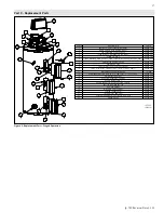
Page 17: ... 55 GAL 6060P 502 9 JUNCTION BOX COVER W SCREWS 6060P 983 10 JUNCTION BOX COVER W KNOCKOUTS W SCREWS 6060P 982 11 TEMP PRESSURE RELIEF VALVE TP1000 12 ALUMINUM ANODE 63 DIA X 12 LENGTH 1 1 16 SOCKET 6060P 008 13 MOUNTING BRACKET 6060P 955 14 ELECTRIC ELEMENT 5500W 6060P 937 15 UPPER THERMOSTAT 6060P 085 16 UPPER THERMOSTAT PROTECTIVE COVER 6060P 994 17 PROTECTIVE INSULATION 6060P 965 18 ACCESS PAN...

Page 18: ...rranty detailed above F This warranty extends only to water heaters utilized in water heating applications that have been properly installed by qualified professionals based upon the manufacturer s installation instructions G It is expressly agreed between HTP and the Owner that repair replacement or refund are the exclusive remedies of the Owner OWNER RESPONSIBILITIES The Owner or Qualified Insta...

Page 19: ...ng a Serial number tag sticker b The product c The product issue failure whenever possible d A picture of the piping near the product e For gas fired products a picture of the venting including how it exits the building All claims will be reviewed by HTP within three 3 business days If additional information is required and requested by the HTP Claims Department you will have thirty 30 days to pro...

Page 20: ...ation Installation Address Product Name Serial Number s Comments Installer s Code Name Installers Phone Number Signed by Installer Signed by Customer Installation Notes IMPORTANT Customer Please only sign after the qualified installer service technician has fully reviewed the installation safety proper operation and maintenance of the system If the system has any problems please call the qualified...

Reviews: