18
LP-171 Rev. 3.3.15
SIZING SPACE HEAT SYSTEM PIPING
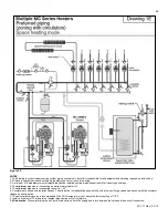
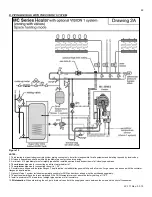
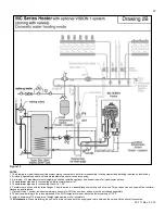
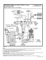
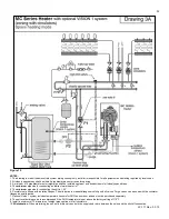
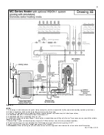
1. See Piping Details in this section. In all diagrams, the space heating system is isolated from the heating loop by the
primary/secondary connection.
2. Size the piping and components in the space heating system using recognized design methods.
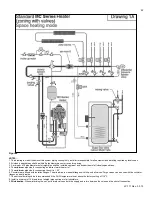
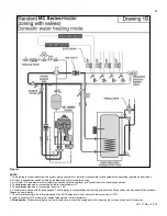
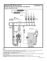
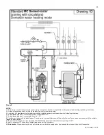
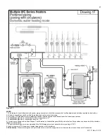
G. HYDRONIC PIPING WITH CIRCULATORS, ZONE VALVES, AND MULTIPLE HEATERS
This heater may function in a closed loop 15 psi system. An optional water pressure switch ensures adequate pressure in the system.
The heater will not operate without a minimum of 10 psi water pressure. This assures you that if the system does have a leak, the
heater will lock out (PRO on the display) before it damages the heat exchanger.
The included temperature and pressure gauge allows the user to monitor the system pressure and outlet temperature from the heater.
It is important to note that the heater has a minimal amount of pressure drop that must be calculated when sizing the circulators. Each
installation must also have an air elimination device that will remove air from the system.
Observe minimum 1” clearance around all un-insulated hot water pipes when openings around pipes are not protected by non-
combustible materials. On a heater installed above radiation level, some states and local codes require a low water cut off device (See
Part C this section). If the heater supplies hot water to heating coils in air handler units, flow control valves or other devices must be
installed to prevent gravity circulation of heater water in the coils during the cooling cycle. Chilled water medium must be piped in
parallel with the heater.
The heater should not be operated as a potable hot water heater. Operating this heater as a potable water heater will VOID warranty.
1. Connect the sy
stem return marked “Heater In”.
2.
Connect the system supply marked “Heater Out”.
3. Install purge and balance valve or shut off valve and drain on system return to purge air out of each zone.
4. Install a back flow preventer on the cold feed make-up water line.
5. Install a pressure reducing valve on the cold feed make-up water line, (15 psi nominal on the system return). Check temperature and
pressure gauge, which should read minimum pressure of 12 psi.
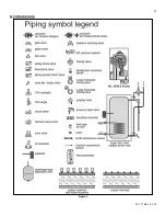
6. Install a circulator as shown in piping details (this section). Make sure the circulator is properly sized for the system and friction loss.
7. Install an expansion tank on the system supply. Consult the tank ma
nufacturer’s instruction for specific information relating to
expansion tank installation. Size the expansion tank for the required system volume and capacity.
8. Install an air elimination device on the system supply.
9. Install a drain valve at the lowest point of the system. NOTE: The heater cannot be drained completely of water without purging the
unit with an air pressure 15 psi.
10. The safety relief valve is installed at the factory. Pipe the discharge of the safety relief valve to prevent injury in the event of
pressure relief. Pipe the discharge 6” above the drain to a drain. Provide piping that is the same size as the safety relief valve outlet.
Never block the outlet of safety relief valve.
H. CIRCULATOR SIZING
The heat exchanger has a minimum total water volume that must be taken into account when sizing the circulator. These minimum
water volumes are listed in Table 3 below.
MINIMUM BOILER FLOW RATES
MODEL
MINIMUM FLOW (GPM)
MC-50
3.3
MC-80
5.3
MC-99
7.8
MC-120
8
Table 3
– Minimum Heat Exchanger Water Volumes
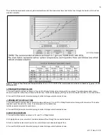
In addition, the heat exchanger has pressure drop which must be considered in your system design. Refer to the graph in
Figure 4
for
pressure drop through the heat exchanger for recommended pump select
ion at a 20∆t design.
Summary of Contents for MC120
Page 21: ...21 LP 171 Rev 3 3 15 M PIPING DETAILS Figure 5 ...
Page 53: ...53 LP 171 Rev 3 3 15 Figure 30 ...
Page 71: ...71 LP 171 Rev 3 3 15 Figure 34 ...
Page 72: ...72 LP 171 Rev 3 3 15 Figure 35 ...
Page 73: ...73 LP 171 Rev 3 3 15 Figure 36 ...
Page 76: ...76 LP 171 Rev 3 3 15 ...
Page 77: ...77 LP 171 Rev 3 3 15 ...

