19
LP-171 Rev. 3.3.15
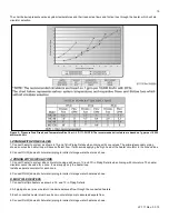
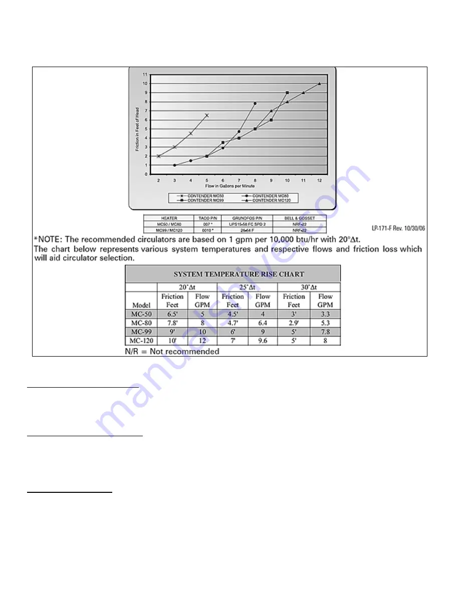
The chart below represents various system temperatures and their respective flows and friction loss through the heater, which will aid
circulator selection.
Figure 4
– Pressure Drop Graph and Temperature Rise Chart – LP-171-F
NOTE: The recommended circulators are based on 1 gpm per 10,000
btu/hr with 20∆t.
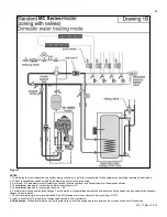
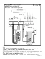
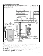
I. ZONING WITH ZONE VALVES
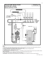
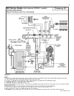
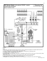
1. Connect heater to system as shown in 1A and 1B in Piping Details when zoning with zone valves. The primary/secondary piping
shown ensures the heater loop will have sufficient flow. It also avoids applying the high head of the heater circulator to the zone valves.
2. Connect DHW (domestic hot water) piping to indirect storage water heater as shown.
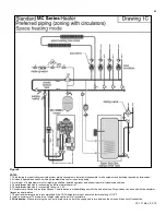
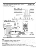
J. ZONING WITH CIRCULATORS
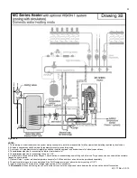
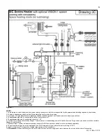
1. Connect heater to system when circulator zoning as shown in 1C and 1D in Piping Details when zoning with circulators. The heater
circulator cannot be used for a zone. It must supply only the heater loop.
Install a separate circulator for each zone.
2. Connect DHW (domestic hot water) piping to indirect storage water heater as shown.
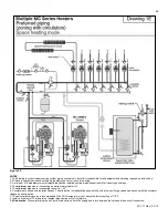
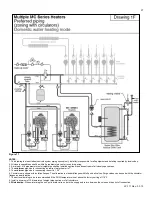
K. MULTIPLE HEATERS
1. Connect multiple heaters as shown in 1E and 1F in Piping Details.
2. All piping shown is reverse return to assure balanced flow through the connected heaters.
3. Each connected heater must have its own circulator pump to assure adequate flow.
4. Connect DHW (domestic hot water) piping to indirect storage water heater as shown.
Summary of Contents for MC120
Page 21: ...21 LP 171 Rev 3 3 15 M PIPING DETAILS Figure 5 ...
Page 53: ...53 LP 171 Rev 3 3 15 Figure 30 ...
Page 71: ...71 LP 171 Rev 3 3 15 Figure 34 ...
Page 72: ...72 LP 171 Rev 3 3 15 Figure 35 ...
Page 73: ...73 LP 171 Rev 3 3 15 Figure 36 ...
Page 76: ...76 LP 171 Rev 3 3 15 ...
Page 77: ...77 LP 171 Rev 3 3 15 ...

