67
LP-171 Rev. 3.3.15
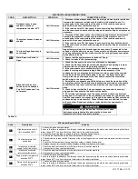
F09
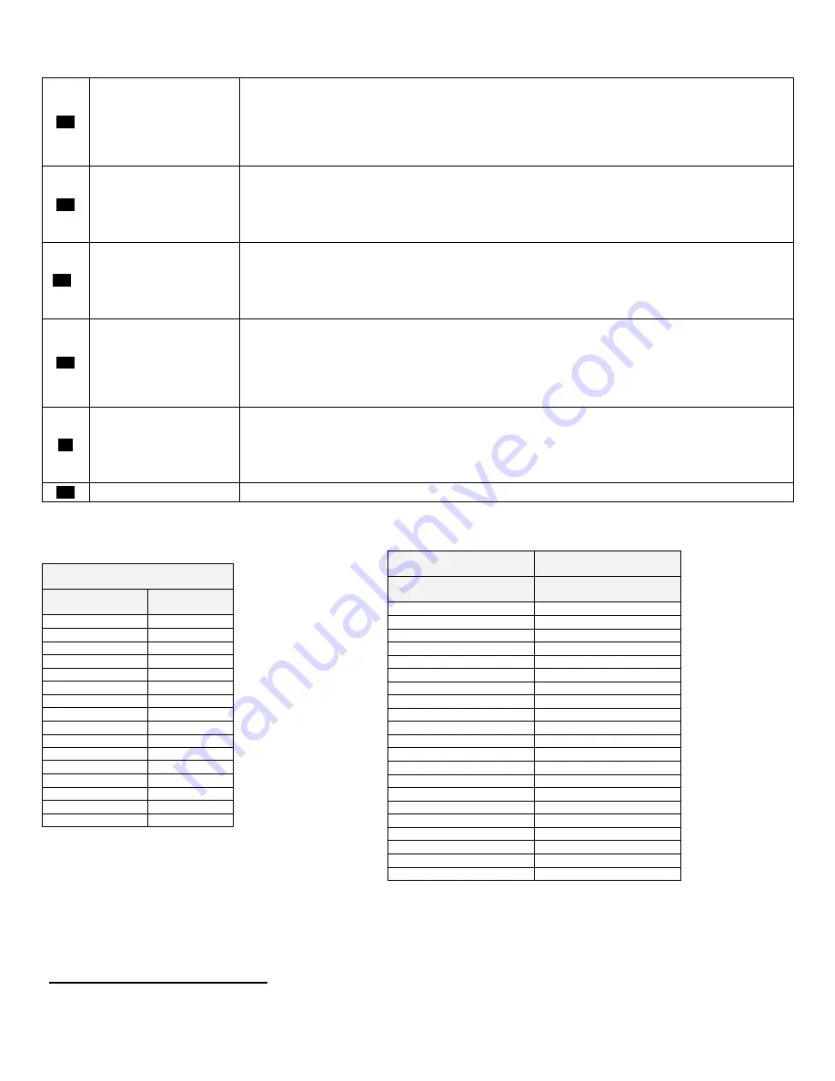
No flame detected
– The
heater will make three
attempts at ignition before
the control goes into this
lockout condition. *See
spark electrode detail.
1. Watch the igniter through the observation window provided.
2. If there is no spark, check the spark electrode for the proper ¼” gap by holding two quarters together and
sliding them through the gap.
3. Remove any corrosion from the spark electrode and flame rectifier probe.
4. If there is a spark but no flame, check the gas supply to the heater.
5. If there is a flame, check the flame sensor.
6. Check any flue blockage or condensate blocks.
F10
Loss of flame signal
– The
heater will relight 4 times
before the control goes into
this lockout condition. Will
reset in 1 hour.
1. Monitor the gas pressure to the unit while in operation.
2. Assure that the flame is stable when lit.
3. Check to see if the green light on the display module is out while the heater is running.
4. If the green light doesn’t come on or goes off during operation check the flame signal on the status menu.
5. If the signal reads less than 1 microampere, clean the flame rectifier probe.
6. If the flame rectifier probe continues to read low, replace it.
F11F
False flame signal
– The
heater will lock out if it
senses a flame signal when
there should be none
present.
1. Turn the gas off to the unit at the service valve.
2. If the flame signal is still present replace the igniter.
3. If the flame signal is not present after turning off the gas supply, check the gas valve electrical connection.
4. If there is no power to the gas valve, remove the valve and check for obstruction in the valve seat or replace
the gas valve.
5. Turn the gas on at the service valve after corrective action is taken.
F13
Combustion fan speed out
of tolerance
– The
appliance will lock out if it
senses that the fan speed
is not at 70% the expected
speed for more than 60
seconds.
1. Check the combustion fan wiring.
2. Replace the combustion fan.
3. Replace the control board.
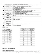
PP
The control has been
programmed by a
technician or the factory.
After programming, the
control is left in a locked out
mode.
Press the RESET key for at least 1 second to begin use of the control.
F31
Parameter Memory
Call factory for further assistance.
Table 15
Resistance Tables
PART 15 – MAINTENANCE
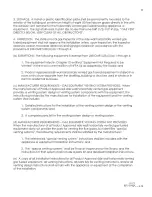
A. MAINTENANCE PROCEDURES
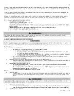
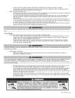
Periodic maintenance should be performed once a year by a qualified service technician to assure that all the equipment is in safe
efficient operation. The owner can make necessary arrangements with a qualified heating contractor for periodic maintenance of the
HEATER SENSOR
(7250P-059)
INDIRECT SENSOR
(7250P-325)
HEATER AND INDIRECT
TEMPERATURE (
o
F)
RESISTANCE (ohms)
32
32550
41
25340
50
19870
59
15700
68
12490
77
10000
86
8059
95
6535
104
5330
113
4372
122
3605
131
2989
140
2490
149
2084
158
1753
167
1481
176
1256
185
1070
194
915
203
786
212
667
OUTDOOR SENSOR
(7250P-319)
OUTSIDE TEMP.
(
o
F)
RESISTANCE
(ohms)
-22
171800
-13
129800
-4
98930
5
76020
14
58880
23
45950
32
36130
41
28600
50
22800
59
18300
68
14770
77
12000
86
9804
95
8054
104
6652
113
5522
Table 16
Table 17
Summary of Contents for MC120
Page 21: ...21 LP 171 Rev 3 3 15 M PIPING DETAILS Figure 5 ...
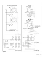
Page 53: ...53 LP 171 Rev 3 3 15 Figure 30 ...
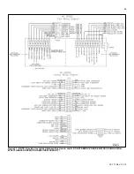
Page 71: ...71 LP 171 Rev 3 3 15 Figure 34 ...
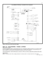
Page 72: ...72 LP 171 Rev 3 3 15 Figure 35 ...
Page 73: ...73 LP 171 Rev 3 3 15 Figure 36 ...
Page 76: ...76 LP 171 Rev 3 3 15 ...
Page 77: ...77 LP 171 Rev 3 3 15 ...

