background image

71 


                                                                                       LP-171 Rev. 3.3.15 


Figure 34 

Summary of Contents for MC120

Page 1: ...RY SETTINGS Refer to the Control Program Reference Chart within this manual for selections that apply to this model This manual must be used by a qualified installer service technician Read all instructions in this manual before installing Perform steps in the given order Failure to comply could result in substantial property damage severe personal injury or death NOTICE HTP reserves the right to ...

Page 2: ...VICINITY OF THIS OR ANY OTHER HEATER WHAT TO DO IF YOU SMELL GAS Do not try to light any appliance Do not touch any electrical switch Do not use any phone in your building Immediately call your gas supplier from a neighbor s phone Follow the gas supplier s instructions If you cannot reach your gas supplier call the fire department Installation and service must be provided by a qualified installer ...

Page 3: ...bor department or health department building official or electrical inspector or others having statutory authority In some circumstances the property owner or his her agent assumes the role and at government installations the commanding officer or departmental official may be the AHJ NOTE HTP Inc reserves the right to modify product technical specifications and components without prior notice FOR ...

Page 4: ...FETY INFORMATION 6 A PRECAUTIONS 6 B IMPROPER COMBUSTION 7 C GAS 7 D WHEN SERVICING THE HEATER 7 E HEATER SYSTEM 7 F WATER CHEMISTRY 7 G WINTERIZING 8 PART 2 BEFORE YOU START 8 A WHAT S IN THE BOX 8 B HOW THE HEATER OPERATES 8 C OPTIONAL EQUIPMENT 10 PART 3 PREPARE HEATER LOCATION 10 A BEFORE LOCATING THE HEATER 10 B LEVELING 11 C CLEARANCES FOR SERVICE ACCESS 12 D RESIDENTIAL GARAGE CLOSET AND AL...

Page 5: ...UST VENT AND INTAKE PIPE 40 C REQUIREMENTS FOR INSTALLATION IN CANADA 40 D EXHAUST VENT AND INTAKE PIPE LOCATION 41 E ROTATING THE FLUE ADAPTER 44 F EXHAUST VENT AND INTAKE PIPE SIZING 45 G LONGER VENT RUNS 45 H EXHAUST VENT AND INTAKE PIPE INSTALLATION 46 I VENTING DRAWINGS 46 PART 8 GAS PIPING 48 A GAS CONNECTION 48 B GAS PIPING 50 C CHECK INLET GAS PRESSURE 50 D GAS VALVE 51 PART 9 FIELD WIRING...

Page 6: ...ON A PRECAUTIONS This heater is for indoor installations only Clearance to combustible materials 0 top bottom sides and back Front must have room for service 24 recommended A combustible door or removable panel is acceptable front clearance This heater has been approved for closet installation This heater is designed to be wall mounted Do not install on the floor Category IV vent systems only INST...

Page 7: ...struct combustion and ventilating air flow Adequate air must be provided for safe operation Failure to keep the exhaust vent and intake pipe clear of ice snow or other debris could result in property damage serious personal injury or death C GAS Should overheating or gas supply fail to shut off do not turn off or disconnect electrical supply to circulator Instead shut off the gas supply at a locat...

Page 8: ...rain valve and allow air and water to escape from the purge valve see piping instructions Once you have evacuated as much water as possible pump non toxic NSF food grade propylene glycol FDA rated as GRAS Generally Recognized As Safe into the system Consult the glycol manufacturer for specific instructions on concentration percentage as well as freeze and burst protection methods Check the volume ...

Page 9: ...trip for power CH pump and DHW pump Route low voltage wires through the opening to the left of the low voltage terminal strip see Field Wiring Instructions Part 9 Condensate Drain Connection As this is a condensing high efficiency appliance the unit has a condensate removal system Condensate is nothing more than water vapor derived from combustion products and similar to an automobile when it is i...

Page 10: ...jury or death Failure of heater or components due to incorrect operating conditions IS NOT covered by product warranty 1 Installation Area Mechanical Room Operating Conditions Ensure ambient temperatures are higher than 32 o F 0 o C and lower than 104 o F 40 o C Prevent the air from becoming contaminated by the products places and conditions listed in this manual Part 3 Section F Avoid continuousl...

Page 11: ...6 Clean and flush system when reinstalling a heater NOTE When installing in a zero clearance location it may not be possible to read or view some product labeling It is recommended to make note of the heater model and serial number Figure 1 Specifications LP 171 B Before considering location many factors need to be addressed Piping Venting and Condensation Removal are just a few of the issues that...

Page 12: ...njury PRECAUTIONS If the heater is located in a residential garage per ANSI Z223 1 Mount the bottom of the heater a minimum of 18 above the floor of the garage to ensure the burner and ignition devices are well off the floor Locate or protect the heater so it cannot be damaged by a moving vehicle For closet or alcove installations a two pipe venting system must be used Failure to follow this warni...

Page 13: ...ribed in the Venting section Do not terminate exhaust in locations that can allow contamination of intake air PRODUCTS TO AVOID AREAS LIKELY TO HAVE CONTAMINANTS Spray cans containing fluorocarbons Dry cleaning laundry areas and establishments Permanent wave solutions Swimming pools Chlorinated waxes cleaners Metal fabrication plants Chlorine based swimming pool chemicals Beauty shops Calcium chlo...

Page 14: ...ette 6 After it has been determined that each appliance remaining connected to common venting system properly vents when tested as outlined return doors windows exhaust fans fireplace dampers and any other gas burning appliance to their previous condition of use 7 Any improper operation of the common venting system should be corrected to conform to the National Fuel Gas Code ANSI Z223 1 When resiz...

Page 15: ...r the screws Then lower the heater onto the smallest part of the keyway slot 3 Once the heater is mounted on the first 2 screws finish tightening the screws to the back panel Then install the 6 additional screws of the same size to the back panel holes This will provide additional strength and support to the heater PART 5 HEATER PIPING Failure to follow the instructions in this section WILL VOID t...

Page 16: ...uld the relief valve discharge Discharge line must be as short as possible and the same size as the valve discharge connection throughout its entire length Discharge line must pitch downward from the valve and terminate at least 6 above the floor drain making discharge clearly visible The discharge line shall terminate plain not threaded with a material serviceable for temperatures of 375 o F or g...

Page 17: ... of pipe all fixtures appliances etc Failure to properly size system expansion could result in wasted time money and possible property damage personal injury or death Undersized expansion tanks cause system water to be lost from relief valve and make up water to be added through fill valve Eventual failure can result due to excessive make up water addition SUCH FAILURE IS NOT COVERED BY WARRANTY 2...

Page 18: ...l VOID warranty 1 Connect the system return marked Heater In 2 Connect the system supply marked Heater Out 3 Install purge and balance valve or shut off valve and drain on system return to purge air out of each zone 4 Install a back flow preventer on the cold feed make up water line 5 Install a pressure reducing valve on the cold feed make up water line 15 psi nominal on the system return Check te...

Page 19: ... the zone valves 2 Connect DHW domestic hot water piping to indirect storage water heater as shown J ZONING WITH CIRCULATORS 1 Connect heater to system when circulator zoning as shown in 1C and 1D in Piping Details when zoning with circulators The heater circulator cannot be used for a zone It must supply only the heater loop Install a separate circulator for each zone 2 Connect DHW domestic hot w...

Page 20: ...pon completion make sure that the fill valve is in automatic position and each zone balance and purge or shut off is in an open position and zone valves are positioned for automatic operation Use only inhibited propylene glycol solutions specially formulated for hydronic systems Ethylene glycol is toxic and can attack gaskets and seals used in hydronic systems Glycol mixtures should not exceed 50 ...

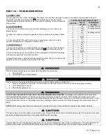
Page 21: ...21 LP 171 Rev 3 3 15 M PIPING DETAILS Figure 5 ...

Page 22: ... for connecting an indirect water heater is 1 5 The minimum pipe size for connecting the unit is 1 25 6 Circulators are shown with isolation flanges The alternative is standard flanges with full port ball valves Purge valves can be used with the circulator flanges as an alternative 7 The anti scald mixing valve is recommended if the DHW temperature is set above the factory setting of 119o F 8 Inst...

Page 23: ... for connecting an indirect water heater is 1 5 The minimum pipe size for connecting the unit is 1 25 6 Circulators are shown with isolation flanges The alternative is standard flanges with full port ball valves Purge valves can be used with the circulator flanges as an alternative 7 The anti scald mixing valve is recommended if the DHW temperature is set above the factory setting of 119o F 8 Inst...

Page 24: ... for connecting an indirect water heater is 1 5 The minimum pipe size for connecting the unit is 1 25 6 Circulators are shown with isolation flanges The alternative is standard flanges with full port ball valves Purge valves can be used with the circulator flanges as an alternative 7 The anti scald mixing valve is recommended if the DHW temperature is set above the factory setting of 119o F 8 Inst...

Page 25: ... for connecting an indirect water heater is 1 5 The minimum pipe size for connecting the unit is 1 25 6 Circulators are shown with isolation flanges The alternative is standard flanges with full port ball valves Purge valves can be used with the circulator flanges as an alternative 7 The anti scald mixing valve is recommended if the DHW temperature is set above the factory setting of 119o F 8 Inst...

Page 26: ...e for connecting an indirect water heater is 1 5 The minimum pipe size for connecting the unit is 1 25 6 Circulators are shown with isolation flanges The alternative is standard flanges with full port ball valves Purge valves can be used with the circulator flanges as an alternative 7 The anti scald mixing valve is recommended if the DHW temperature is set above the factory setting of 119o F 8 Ins...

Page 27: ...e for connecting an indirect water heater is 1 5 The minimum pipe size for connecting the unit is 1 25 6 Circulators are shown with isolation flanges The alternative is standard flanges with full port ball valves Purge valves can be used with the circulator flanges as an alternative 7 The anti scald mixing valve is recommended if the DHW temperature is set above the factory setting of 119o F 8 Ins...

Page 28: ...ONING WITH ZONE VALVES USING VISION 1 1 Connect the heater to the system as shown in piping details 2A through 2C 2 Connect the DHW circulator P2 directly to the heater as shown in the piping details The heater circulator P1 will shut down when there is a DHW demand C ZONING WITH CIRCULATORS USING VISION 1 1 Connect the heater to the system as shown in piping details 3A through 3G 2 Connect the DH...

Page 29: ...eater is 1 5 The minimum pipe size for connecting the unit is 1 25 6 Circulators are shown with isolation flanges The alternative is standard flanges with full port ball valves Purge valves can be used with the circulator flanges as an alternative 7 Optional Vision 1 system includes temperature sensors for DHW and outdoor air and must be purchased separately 8 The anti scald mixing valve is recomm...

Page 30: ...mum pipe size for connecting the unit is 1 25 6 Circulators are shown with isolation flanges The alternative is standard flanges with full port ball valves Purge valves can be used with the circulator flanges as an alternative 7 Optional Vision 1 system includes temperature sensors for DHW and outdoor air and must be purchased separately 8 The anti scald mixing valve is recommended if the DHW temp...

Page 31: ...mum pipe size for connecting the unit is 1 25 6 Circulators are shown with isolation flanges The alternative is standard flanges with full port ball valves Purge valves can be used with the circulator flanges as an alternative 7 Optional Vision 1 system includes temperature sensors for DHW and outdoor air and must be purchased separately 8 The anti scald mixing valve is recommended if the DHW temp...

Page 32: ...mum pipe size for connecting the unit is 1 25 6 Circulators are shown with isolation flanges The alternative is standard flanges with full port ball valves Purge valves can be used with the circulator flanges as an alternative 7 Optional Vision 1 system includes temperature sensors for DHW and outdoor air and must be purchased separately 8 The anti scald mixing valve is recommended if the DHW temp...

Page 33: ...mum pipe size for connecting the unit is 1 25 6 Circulators are shown with isolation flanges The alternative is standard flanges with full port ball valves Purge valves can be used with the circulator flanges as an alternative 7 Optional Vision 1 system includes temperature sensors for DHW and outdoor air and must be purchased separately 8 The anti scald mixing valve is recommended if the DHW temp...

Page 34: ...mum pipe size for connecting the unit is 1 25 6 Circulators are shown with isolation flanges The alternative is standard flanges with full port ball valves Purge valves can be used with the circulator flanges as an alternative 7 Optional Vision 1 system includes temperature sensors for DHW and outdoor air and must be purchased separately 8 The anti scald mixing valve is recommended if the DHW temp...

Page 35: ...mum pipe size for connecting the unit is 1 25 6 Circulators are shown with isolation flanges The alternative is standard flanges with full port ball valves Purge valves can be used with the circulator flanges as an alternative 7 Optional Vision 1 system includes temperature sensors for DHW and outdoor air and must be purchased separately 8 The anti scald mixing valve is recommended if the DHW temp...

Page 36: ...mum pipe size for connecting the unit is 1 25 6 Circulators are shown with isolation flanges The alternative is standard flanges with full port ball valves Purge valves can be used with the circulator flanges as an alternative 7 Optional Vision 1 system includes temperature sensors for DHW and outdoor air and must be purchased separately 8 The anti scald mixing valve is recommended if the DHW temp...

Page 37: ...mum pipe size for connecting the unit is 1 25 6 Circulators are shown with isolation flanges The alternative is standard flanges with full port ball valves Purge valves can be used with the circulator flanges as an alternative 7 Optional Vision 1 system includes temperature sensors for DHW and outdoor air and must be purchased separately 8 The anti scald mixing valve is recommended if the DHW temp...

Page 38: ...mum pipe size for connecting the unit is 1 25 6 Circulators are shown with isolation flanges The alternative is standard flanges with full port ball valves Purge valves can be used with the circulator flanges as an alternative 7 Optional Vision 1 system includes temperature sensors for DHW and outdoor air and must be purchased separately 8 The anti scald mixing valve is recommended if the DHW temp...

Page 39: ...ions of local building codes 3 This water heater must be vented with materials components and systems listed and approved for Category IV appliances Exhaust vent and intake pipes are to be piped separately This heater cannot share a common exhaust or intake with multiple appliances Failure to follow this instruction will result in substantial property damage severe personal injury or death NOTE To...

Page 40: ...ement specifically designed for the material used as listed in Table 4 Failure to do so could result in property damage severe personal injury or death Exhaust vent adaptors are not designed as load bearing devices and must not be used to support exhaust vent piping All vent pipes must be glued properly supported and the exhaust must be pitched a minimum of per foot back to the heater to allow dra...

Page 41: ...f equipment exhaust fans and inlets In no case shall the exit terminal be above or below the aforementioned equipment unless the 4 foot horizontal distance is maintained J This water heater vent system shall terminate at least 3 feet 0 9 m above any forced air intake located within 10 ft 3 m NOTE This does not apply to the combustion air intake of a direct vent appliance K When venting with a two ...

Page 42: ...jurisdiction In the absence of other authority PVC and CPVC pipe must comply with ASTM D1785 or D2845 Cement and primer must comply with ASME D2564 or F493 For Canada use CSA or ULC certified PVC or CPVC pipe fittings and cement If pipe is used deburr and chamfer pipe to allow proper mating to the drainage assembly NOTE To allow for proper drainage on long horizontal runs a second line vent may be...

Page 43: ...g temperatures or any type of blockage Damages due to frozen or blocked condensate lines ARE NOT covered by warranty 4 Support of the condensate line may be necessary to avoid blockage of the condensate flow If using a condensate pump select one approved for use with condensing heaters and furnaces The pump should have an overflow switch to prevent property damage from condensate spillage It is ve...

Page 44: ...oved NOTE DO NOT glue optional polypropylene vent system To rotate the flue adapter 1 Remove the black heater cover 2 Inspect the area where the white flue adapter mates to the black plastic heat exchanger You will notice two red wires and a plastic hose connected to the flue adapter These will limit the rotation range of the flue adapter 3 Grasp the entire white PVC flue adapter and rotate it in ...

Page 45: ...used we find Total Equivalent Length 20 23 3 46 feet Therefore the total equivalent length is 46 feet which is well below the maximum of 85 feet c The exhaust vent and intake pipe are intended to penetrate the same wall or roof of the building d Effort should be made to keep a minimum difference in equivalent length between the exhaust vent and intake pipe 3 The minimum total equivalent length is ...

Page 46: ...ferred venting option To save time and cost carefully consider venting installation and location 10 Horizontal lengths of exhaust vent must slope back towards the heater not less than per foot to allow condensate to drain from the vent pipe 11 The exhaust vent must terminate where vapors cannot make accidental contact with people or pets or damage shrubs or plants 12 In vacant chimney applications...

Page 47: ...could result in property damage serious personal injury or death due to flue gas leakage Figure 26 Two Pipe Roof and Sidewall Venting with Included Equipment Tee and Coupling NOTE These drawings are meant to demonstrate system venting only The installer is responsible for all equipment and detailing required by local codes All vent pipes must be glued properly supported and the exhaust must be pit...

Page 48: ...te When placing support brackets on vent piping the first bracket must be within 1 foot of the water heater and the balance at 4 foot intervals on the vent pipe Heater venting must be readily accessible for visual inspection for the first three feet from the heater PART 8 GAS PIPING Failure to follow all precautions in this section could result in fire explosion severe injury or death A GAS CONNEC...

Page 49: ...as valve In the event the gas valve is exposed to a pressure greater than PSI 14 water column the gas valve must be replaced Never use an open flame match lighter etc to check gas connections Refer to the table below to size the supply piping to minimize pressure drop between meter or regulator and unit Maximum capacity of pipe in cubic feet of gas per hour for gas pressures of 5 psi or less and a...

Page 50: ... when tightening gas piping near the heater and its piping connection One wrench to prevent the heater gas line connection from turning the second to tighten the adjacent piping Failure to support the heater gas piping connection could damage the heater beyond repair Such damage IS NOT covered by warranty C CHECK INLET GAS PRESSURE The gas valve is equipped with an inlet gas pressure tap that can ...

Page 51: ...gulator is used it must be installed a minimum of 10 feet from the heater It is very important that the gas line is properly purged by the gas supplier or utility Failure to properly purge the lines or improper line sizing will result in ignition failure This problem is especially noticeable in NEW LP installations and empty tank situations This situation can also occur when a utility company shut...

Page 52: ...ns could result in property damage or personal injury A INSTALLATION MUST COMPLY WITH National Electrical Code and any other national state provincial or local codes or regulations In Canada CSA C22 1 Canadian Electrical Code Part 1 and any local codes B FIELD WIRING For your convenience we have located the electrical connection of the heater on the front right hand side of the unit The electrical...

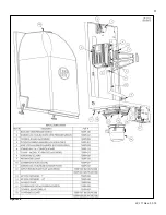
Page 53: ...53 LP 171 Rev 3 3 15 Figure 30 ...

Page 54: ...54 LP 171 Rev 3 3 15 Figure 31 NOTE A resistor is provided between Bus Lines A and B DO NOT REMOVE THIS RESISTOR DOING SO WILL EFFECT HEATER OPERATION AND VOID WARRANTY ...

Page 55: ...stallation Once the outdoor sensor light green wires is connected to the control board the water temperature of the heater will adjust to run the heater more efficiently and provide greater comfort to the living space Connection Specification Wire 22 AWG maximum to 100 feet or 18 AWG up to 150 feet Length of wire run cannot exceed 150 feet Outdoor Sensor NOTE If the system requires a fixed operati...

Page 56: ... control the temperature of the indirect from the heater and give the indirect priority over the central heating circuit Once the indirect is satisfied the heater will then switch back to central heating if there is a call for heat If not the heater will then shut down Caution should be used to ensure neither of these terminals becomes connected to ground NOTE If sensor wires are located in an are...

Page 57: ... mGL Water pH between 6 0 and 8 0 1 Maintain heater water pH between 6 0 and 8 0 Check with litmus paper or have chemically analyzed by water treatment company 2 If pH differs from above consult local water treatment company for treatment needed Hardness less than 7 grains Consult local water treatment companies for unusually hard water areas above 7 grains hardness Chlorine concentration less tha...

Page 58: ...stem pressure Correct pressure will vary with each application a Typical cold water fill pressure for a residential system is 12 psi b Pressure will rise when heater is turned on and system water temperature increases Operating pressure must never exceed 25 psig 4 At initial fill and during heater startup and testing check system thoroughly for any leaks Repair all leaks before proceeding further ...

Page 59: ...her at any time will return the heater control to normal operation NOTE IF THE INSTALLER DOES NOT CANCEL THIS FUNCTION BY PRESSING S1 AND S2 TOGETHER THE PUMPS WILL RUN FOR A MAXIMUM OF 20 MINUTES AND SHUT OFF AUTOMATICALLY 9 While the pump is running as described above open the manual air vent on the front of the heat exchanger as shown in Fig 31 to further assist in removing air from the system ...

Page 60: ...uit wiring is checked and corrected if necessary reconnect the external thermostat circuit wires to heater low voltage terminal strip Allow the heater to cycle H CONDENSATE REMOVAL 1 This a high efficiency condensing heater there the unit has a condensation drain Condensate is nothing more than water vapor derived from combustion products similar to an automobile when it is initially started The c...

Page 61: ...you smell gas STOP Follow listed safety instructions If you do not smell gas follow the next steps 1 Turn on all electric power to heater 2 If desired adjust the temperature set point of the heater The factory default setting is 180 o F If changes are necessary follow Adjusting the Set point in this section 3 Set the thermostat to the desired setting 4 If the heater fails to start refer to the Tro...

Page 62: ...of the Indirect Fired Circulator Off 0 On 1 Vision option d10 Actual Status bus communication co connected no not connected d11 Central Heating Set Point d12 Power On Hours in units d13 Total Central Heat Hours d14 Total Indirect dhw Hours d15 Passed Ignition Attempts D TEST MODE This function is intended to simplify the gas valve adjustment if needed Listed below are the recommended limits on eac...

Page 63: ...art 13 to set outdoor reset curve START UP PROCEDURES WITH VISION 1 OPTION DEFAULT FUNCTION FUNCTION VALUE DESCRIPTION 1 de Not Applicable 2 149 o F Not Applicable 3 160 o F Maximum domestic delivery water temperature set point the installer will program for indirect water heater NOTE Does not apply if used with mechanical control Range 95 o F to 160 o F 4 36 o F Not Applicable 5 7 o F Allows the ...

Page 64: ...ses When an outside sensor is also connected the supply temperature will depend on the factory default central heating curve To set your heat curve you will have to set the following parameters 1 Minimum outside design temperature Function 8 Table 12 Central Heating Curve Factory Default 2 Design supply water temperature at the minimum design outside temperature Function 9 3 Maximum outside design...

Page 65: ... certain that There is no pressure in the heater Pull the release on the relief valve Do not rely on the pressure gauge reading The heater water is not hot The electrical power is off DO NOT USE THIS HEATER IF ANY PART HAS BEEN SUBMERGED IN WATER Immediately call a qualified service technician The heater MUST BE replaced if it has been submerged Attempting to operate an heater that has been submer...

Page 66: ... is open or shorted Until Corrected 1 Disconnect the system sensor from the wiring and measure its resistance Compare the measured resistance to the table in this manual to see if it corresponds to the temperature of the sensor If the resistance does not agree with the sensor replace the sensor 2 If the resistance is OK disconnect the sensor wiring from both the boiler and the sensor and check con...

Page 67: ...ot present after turning off the gas supply check the gas valve electrical connection 4 If there is no power to the gas valve remove the valve and check for obstruction in the valve seat or replace the gas valve 5 Turn the gas on at the service valve after corrective action is taken F13 Combustion fan speed out of tolerance The appliance will lock out if it senses that the fan speed is not at 70 t...

Page 68: ...diately Breathing Fresh Air B MAINTENANCE SCHEDULE FOR THE SERVICE TECHNICIAN The following maintenance should be performed annually by a qualified service technician General Attend to any reported problems Inspect the interior of the heater jacket area clean and vacuum if necessary Clean the condensate trap and fill with fresh water Check for water gas flue and condensate leaks Verify flue vent p...

Page 69: ...es are found Remove contaminates immediately from area If contaminates have been in the area for an extended period call a qualified service technician to inspect the unit for possible acid corrosion damage If contaminates cannot be removed immediately call a qualified service technician to re pipe the combustion air inlet piping and locate the intake away from contaminated areas o Do not store co...

Page 70: ... on p 2 Call a qualified service technician o Visually inspect for leaks around the internal heater water connections and around the heat exchanger Visually inspect the external system piping circulators and system components and fittings Immediately call a qualified service technician to repair any leaks Have gas leaks fixed at once by a qualified service technician Failure to comply could result...

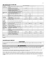
Page 71: ...71 LP 171 Rev 3 3 15 Figure 34 ...

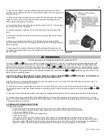
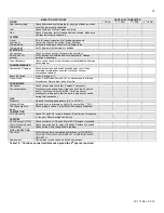
Page 72: ...72 LP 171 Rev 3 3 15 Figure 35 ...

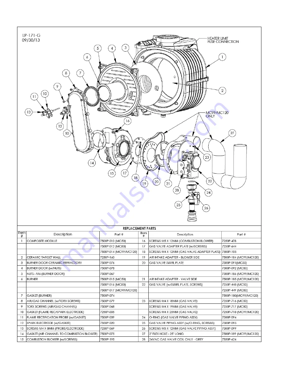
Page 73: ...73 LP 171 Rev 3 3 15 Figure 36 ...

Page 74: ...ter If necessary convert the heater to the proper gas type Locate the stickers in the appropriate locations on the heater Verify combustion settings after gas conversion Carbon Dioxide ____ CO2 High Fire ____ CO2 Low Fire Verify combustion settings after gas conversion Carbon Monoxide ____ppm CO High Fire ____ppm CO Low Fire Mail in the conversion registration Notes Table 18 MAINTENANCE REPORT In ...

Page 75: ...ode Clean Set gap at Flame Probe Clean Check ionization in uA d7 on status menu in Start up Procedures Record high fire and low fire CONDENSATE Neutralizer Check condensate neutralizer Replace if necessary Condensate hose Disconnect condensate hose Clean out dirt Fill with water to level of outlet and re install NOTE Verify the flow of condensate making sure that the hose is properly connected dur...

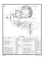
Page 76: ...76 LP 171 Rev 3 3 15 ...

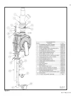
Page 77: ...77 LP 171 Rev 3 3 15 ...

Page 78: ...78 LP 171 Rev 3 3 15 MAINTENANCE NOTES ...

Page 79: ...tallation Address Date of Installation Installer s Code Name Product Serial Number s Comments Installer s Phone Number Signed by Installer Signed by Customer IMPORTANT NOTES Customer Please only sign after the installer has reviewed the installation safety proper operation and maintenance of the system In the case that the system has any problems please call the installer If you are unable to make...

Reviews: