background image

36 


                                                                                     LP- 428 REV. 9.2.14 

2. ROOM AIR, INDOOR COMBUSTION, AND VENTILATION AIR 
INSTALLATION REQUIREMENTS 

When using an indoor combustion air installation, the mechanical room MUST be 
provided with properly sized openings, and/or be of sufficient volume to assure 
adequate combustion air and proper ventilation for all gas fired appliances in the 
mechanical room to assure adequate combustion air and proper ventilation. The 
requirements shown here are for the boiler only. Additional gas fired appliances in 
the mechanical room will require an increase in the net free area and/or volume to 
supply adequate combustion air for all appliances. This must be done in 
accordance with the National Fuel Gas Code, NFPA 54 / ANSI Z223.1. 
 
This boiler can be vented using mechanical room air only for combustion. No 
combustion air openings are needed when the boiler is installed in a space with a 
volume NO LESS than 50 cubic feet per 1,000 BTU/hr of all installed gas fired 
appliances and the building MUST NOT BE of “Tight Construction”. 


TIGHT CONSTRUCTION:

 A building with less than .4 ACH (air changes per hour). 

For buildings of “Tight Construction”, provide air openings into the building from the 
outside.


Indoor and outdoor combustion air may be combined by applying a ratio of 
available volume to required volume times the required outdoor air opening(s) 
size(s). This must be done in accordance with the National Fuel Gas Code, NFPA 
54 / ANSI Z223.1. 
 
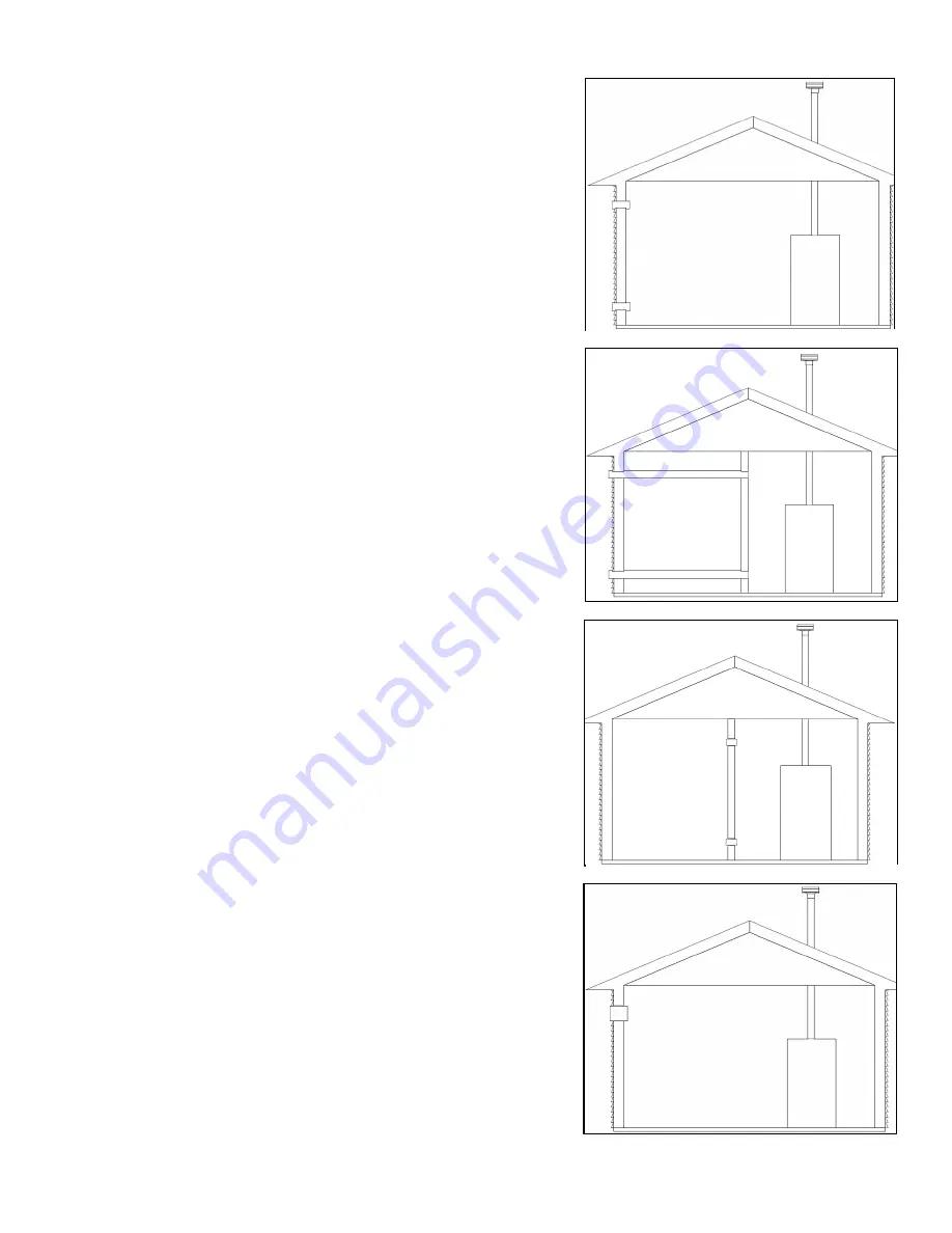
1. If air is taken directly from outside the building with no duct, provide two 
permanent openings to the mechanical room each with a net free area of one 
square inch per 4000 BTU/hr input. See Figure 17. 
 
2. If combustion and ventilation air is taken from the outdoors using a duct to 
deliver the air to the mechanical room, each of the two openings should be sized 
based on a minimum free area of one square inch per 2000 BTU/hr input. See 
Figure 18. 
 
3. If air is taken from another interior space combined with the mechanical room: 
 

a. Two spaces on same story: Each of the two openings specified 


should have a net free area of one square inch for each 1000 BTU/hr 


input, but not less than 100 square inches. 


b. Two spaces on different stories: One or more openings should have   a 


net free area of two square inches per 1000 BTU/hr. 

 
See Figure 19 for reference. 
 
4. If a single combustion air opening is provided to bring combustion air in directly 
from the outdoors, the opening must be sized based on a minimum free area of 
one square inch per 3000 BTU/hr. This opening must be located within 12” of the 
top of the enclosure. See Figure 20. 
 

Combustion air requirements are based on the latest edition of the National Fuel 
Gas Code, NFPA 54 / ANSI Z223.1, CGA Standard CAN/CSA B149.1 in Canada. 
Check all local code requirements for combustion air. 
 
All dimensions based on net free area in square inches. Metal louvers or screens 
reduce the free area of a combustion air opening a minimum of approximately 
25%. Check with louver manufacturers for exact net free area of louvers. 
 
Where two openings are provided, one must be within 12” of the ceiling, and one 
must be within 

12”of the floor of the mechanical room. Each opening must have a 

net free area as specified in Table 9

. Single openings shall commence within 12” 

of the ceiling. The minimum dimension of air openings should not be less than 3”. 
 

Figure 17 

– Combustion Air From Outdoors 

Figure 18 

– Combustion Air Through Ductwork 

Figure 19 

– Combustion Air From Indoors 

Figure 20 

– Combustion Air From Outdoors – Single Opening 

Summary of Contents for MODCON1000

Page 1: ... 2013 Heat Exchanger Bears the ASME H Stamp NOTICE HTP reserves the right to make product changes or updates without notice and will not be held liable for typographical errors in literature NOTE TO CONSUMER PLEASE KEEP ALL INSTRUCTIONS FOR FUTURE REFERENCE This manual must only be used by a qualified heating installer service technician Read all instructions in this manual before installing Perfo...

Page 2: ...CINITY OF THIS OR ANY OTHER APPLIANCE WHAT TO DO IF YOU SMELL GAS Do not try to light any appliance Do not touch any electrical switch Do not use any phone in your building Immediately call your gas supplier from a neighbor s phone Follow the gas supplier s instructions If you cannot reach your gas supplier call the fire department Installation and service must be provided by a qualified installer...

Page 3: ...individual such as a fire chief fire marshal chief of a fire prevention bureau labor department or health department building official or electrical inspector or others having statutory authority In some circumstances the property owner or his her agent assumes the role and at government installations the commanding officer or departmental official may be the AHJ NOTE HTP Inc reserves the right to...

Page 4: ...integrated into the 926 control provided with this heating appliance complies with the requirements of CSD 1 Section CW 400 as a temperature operation control The control monitors the temperature difference between the inlet and the outlet sensor which is affected by boiler water flow If this temperature difference exceeds 55 F typically because of low water flow or very low heat load the control ...

Page 5: ...NSATE REMOVAL 26 A GENERAL 26 B APPROVED MATERIALS FOR EXHAUST VENT AND INTAKE PIPE 26 D REQUIREMENTS FOR INSTALLATION IN CANADA 27 E EXHAUST VENT AND INTAKE PIPE LOCATION 28 F EXHAUST VENT AND INTAKE PIPE SIZING 31 G EXHAUST VENT AND INTAKE PIPE INSTALLATION 31 H BOILER REMOVAL FROM A COMMON VENT SYSTEM 32 I VENTING DRAWINGS 32 1 DIRECT VENT INSTALLATION OF EXHAUST VENT AND INTAKE PIPE 32 2 ROOM ...

Page 6: ... CONDENSATE REMOVAL 51 H FINAL CHECKS BEFORE STARTING BOILER 52 I CASCADE SYSTEM MOD CON 1000 AND 1700 MODELS 52 PART 9 START UP PROCEDURE 53 A CONTROL OVERVIEW 53 B NAVIGATION OF THE DISPLAY 53 C OPERATING INSTRUCTIONS 54 D PROGRAMMING BOILER SETTINGS 54 E PROGRAMMING THE SYSTEM SETTING 55 F SYSTEM SETTING PROGRAM NAVIGATION 55 G RESETTING THE MAINTENANCE SCHEDULE 57 PART 10 START UP PROCEDURES F...

Page 7: ...armful conditions such as a potential gas leakage causing a fire and or explosion or the release of mold bacteria or other harmful particulates into the air Operating a previously submerged appliance could result in property damage severe personal injury or death NOTE Appliance damage due to flood or submersion is considered an Act of God and IS NOT covered under product warranty NOTE If the boile...

Page 8: ...damaged by build up or corrosion due to sediment G FREEZE PROTECTION NEVER use any toxic chemical including automotive standard glycol antifreeze or ethylene glycol made for hydronic non potable systems These chemicals can attack gaskets and seals in water boilers are poisonous if consumed and can cause injury or death Consider piping and installation when determining boiler location NOTE Damages ...

Page 9: ... System Sensor This sensor is mounted in the boiler common piping and monitors the water temperature of the outlet of both boilers simultaneously The master boiler uses this sensor as its primary feedback to control the outlet water temperature of a cascaded boiler system Temperature and Pressure Gauge Allows the user to monitor system temperature and pressure Electrical field connections with ter...

Page 10: ...idity Never close existing ventilation openings The service life of the boiler s exposed metallic surfaces such as the casing as well as internal surfaces such as the heat exchanger are directly influenced by proximity to damp and salty marine environments In such areas higher concentration levels of chlorides from sea spray coupled with relative humidity can lead to degradation of the heat exchan...

Page 11: ...can result in structural failure substantial property damage severe personal injury or death This boiler is approved for installation on combustible flooring but must never be installed on carpeting Installing this boiler on carpeting could result in fire explosion property damage severe personal injury or death C LEVELING AND DIMENSIONS NOTE It is recommended that the boiler be installed on a 4 6...

Page 12: ...it from the space Space must be provided with combustion ventilation air openings correctly sized for all appliances located in the same space as the boiler The boiler venting cover must be securely fastened to prevent it from drawing air from the boiler room This is particularly important if the boiler is in a room with other appliances Failure to comply with the above warnings could result in su...

Page 13: ... are not designed to carry heavy weight Vent support brackets must be within 1 of the appliance and the balance at 4 intervals Appliance must be readily accessible for visual inspection for the first 3 from the appliance 1 DIRECT VENT INSTALLATION OF EXHAUST VENT AND INTAKE PIPE If installing a direct vent option combustion air must be drawn from the outdoors directly into the appliance intake and...

Page 14: ...building of tight construction air for combustion must be obtained from the outdoors as outlined in the Venting Section of this manual When drawing combustion air from the outside into the mechanical room care must be taken to provide adequate freeze protection Do not attempt to vent this appliance by any means other than those described in this manual Doing so will void the warranty and may resul...

Page 15: ...ppliance remaining connected to common venting system properly vents when tested as outlined return doors windows exhaust fans fireplace dampers and any other gas burning appliance to their previous condition of use 7 Any improper operation of the common venting system should be corrected so the installation conforms to the National Fuel Gas Code ANSI Z223 1 When resizing any portion of the common...

Page 16: ...e line in a manner that will prevent possibility of severe burns or property damage should the relief valve discharge Discharge line must be as short as possible and the same size as the valve discharge connection throughout its entire length Discharge line must pitch downward from the valve and terminate at least 6 above the floor drain making discharge clearly visible Discharge line shall termin...

Page 17: ...S DO NOT use the boiler circulator in any location other than the ones shown in this manual The boiler circulator location is selected to ensure adequate flow through the boiler Failure to comply with this caution could result in unreliable performance and nuisance shutdowns from insufficient flow SIZING SPACE HEAT SYSTEM PIPING 1 In all diagrams the space heating system is isolated from the boile...

Page 18: ...on the cold feed make up water line 5 Install a pressure reducing valve on the cold feed make up water line 15 PSI nominal on the system return Check temperature and pressure gauge when operating It should read a minimum pressure of 12 PSI 6 Install a circulator as shown in piping details this section Make sure the circulator is properly sized for the system and friction loss 7 Install an expansio...

Page 19: ...RE RISE CHART 20 o t 25 o t 30 o t MODEL Friction Feet Flow GPM Friction Feet Flow GPM Friction Feet Flow GPM MODCON1000 19 100 11 80 8 66 MODCON1700 35 170 26 130 18 109 Table 4 Temperature Rise Chart Figure 6 represents the combined flow rates and pipe sizes when using multiple boilers to design the manifold system for the primary circuit To size simply add up the number of boilers and the requi...

Page 20: ... iron radiation and systems with manual vents at the high points follow previous section and starting with the nearest manual air vent open until water flows out Then close vent Repeat procedure working your way toward the furthest air vent It may be necessary to install a basket strainer in an older system where larger amounts of sediment may be present Annual cleaning of the strainer may be nece...

Page 21: ... heat transfer coefficients J ZONING WITH ZONE VALVES 1 Connect the boiler to the system as shown in Boiler Piping Details when zoning with zone valves The primary secondary piping shown ensures the boiler loop will have sufficient flow It also avoids applying the high head of the boiler circulator to the zone valves 2 Connect DHW domestic hot water piping to indirect storage water heater K ZONING...

Page 22: ...l circulators 4 Install a minimum of 6 diameters of straight pipe up and downstream of all closely spaced tees 5 Piping shown is Primary Secondary 6 The minimum pipe size for connecting an HTP indirect fired water heater is 1 7 The minimum pipe size for connecting a Mod Con boiler is 3 for both the 1000 and 1700 models 8 System flow Secondary Loop must be greater than the boiler s Primary Loop flo...

Page 23: ...ely spaced tees 5 Piping shown is Primary Secondary 6 The minimum pipe size for connecting an HTP indirect fired water heater is 1 7 The minimum pipe size for connecting a Mod Con boiler is 3 for both the 1000 and 1700 models See Multiple Boiler Manifold Piping chart Figure 6 in this manual when sizing and installing a multiple boiler system 8 System flow Secondary Loop must be greater than the bo...

Page 24: ...pstream of all circulators 3 Install a minimum of 6 diameters of straight pipe up and downstream of all closely spaced tees 4 Piping shown is Primary Secondary 5 The minimum pipe size for connecting a Mod Con boiler is 3 minimum for both the 1000 and 1700 models 6 System flow Secondary Loop must be greater than the boiler s Primary Loop flow 7 Installations must comply with all local codes ...

Page 25: ... up and downstream of all closely spaced tees 4 Piping shown is Primary Secondary 5 The minimum pipe size for connecting a Mod Con boiler is 3 for both the 1000 and 1700 models See Multiple Boiler Manifold Piping chart Figure 6 in this manual when sizing and installing a multiple boiler system 6 System flow Secondary Loop must be greater than the boiler s Primary Loop flow 7 Installations must com...

Page 26: ...ed separately This boiler cannot share a common exhaust or intake with multiple appliances Failure to follow this instruction will result in substantial property damage severe personal injury or death NOTE To avoid contamination often contained in indoor air it is best to pipe all intake combustion air directly to the outdoors NOTE If exhaust vent pipe system passes through an unheated space such ...

Page 27: ...er and cement and adapters specifically designed for the material used as listed in Table 5 Failure to do so could result in property damage severe personal injury or death Exhaust vent adaptors are not designed as load bearing devices and must not be used to support exhaust vent piping All vent pipes must be glued properly supported and the exhaust must be pitched a minimum of per foot back to th...

Page 28: ...s and inlets In no case shall the exit terminal be above or below the aforementioned equipment unless the 4 foot horizontal distance is maintained J This water heater vent system shall terminate at least 3 feet 0 9 m above any forced air intake located within 10 ft 3 m NOTE This does not apply to the combustion air intake of a direct vent appliance K When venting with a two pipe system maximum dis...

Page 29: ...ate piping material APPROVED PLASTIC CONDENSATE PIPING MATERIAL MATERIAL STANDARDS FOR INSTALLATION IN UNITED STATES CANADA PVC SCHEDULE 40 80 ANSI ASTM D1785 ULC S636 Table 6 Approved Plastic Condensate Piping Material NOTE Check with your local gas company to determine if combustion condensate disposal is permitted in your area In the state of Massachusetts condensate must be neutralized before ...

Page 30: ...tee in the line after the condensate neutralizer to properly reduce vacuum lock in the drain line 2 Plastic pipe should be the only material used for the condensate line Steel brass copper or other materials will be subject to corrosion or deterioration 3 NEVER install condensate lines outside It is very important that the condensate line is not exposed to freezing temperatures or any type of bloc...

Page 31: ...ple If the exhaust vent has two short 90 o elbows and 10 feet of PVC pipe we will calculate Exhaust Vent Equivalent Length 2x3 10 16 feet Further if the intake pipe has two short 90 o elbows one 45 o elbow and 10 feet of PVC pipe the following calculation applies Intake Pipe Equivalent Length 2x3 1 10 17 feet 3 The exhaust vent and intake pipe are intended to penetrate the same wall or roof of the...

Page 32: ...ighting instructions Adjust the thermostat so the appliance will operate continuously 5 Test for spillage at the draft hood relief opening after 5 minutes of main burner operation Use the flame of a match or candle or smoke from a cigarette 6 After it has been determined that each appliance remaining connected to common venting system properly vents when tested as outlined return doors windows exh...

Page 33: ... Steel All vent pipes must be glued properly supported and the exhaust must be pitched a minimum of per foot back to the boiler to allow drainage of condensate Exhaust connection insertion depth should be a minimum of 2 for 1000 models and 3 for 1700 models When placing support brackets on vent piping the first bracket must be within 1 of the appliance and the balance at 4 intervals on the vent pi...

Page 34: ...3 for 1700 models When placing support brackets on vent piping the first bracket must be within 1 of the appliance and the balance at 4 intervals on the vent pipe Boiler venting must be readily accessible for visual inspection for the first three feet from the boiler Take extra precaution to adequately support the weight of vent pipes terminating through the roof Failure to properly support roof t...

Page 35: ...sonal injury or death due to flue gas leakage All vent pipes must be glued properly supported and the exhaust must be pitched a minimum of per foot back to the boiler to allow drainage of condensate Exhaust connection insertion depth should be a minimum of 2 for 500 models and 3 for 850 When placing support brackets on vent piping the first bracket must be within 1 of the appliance and the balance...

Page 36: ...mbustion and ventilation air is taken from the outdoors using a duct to deliver the air to the mechanical room each of the two openings should be sized based on a minimum free area of one square inch per 2000 BTU hr input See Figure 18 3 If air is taken from another interior space combined with the mechanical room a Two spaces on same story Each of the two openings specified should have a net free...

Page 37: ...500 500 1000 1000 2000 335 MODCON1700 425 425 850 850 1700 1700 3400 570 Table 9 Indoor Combustion Air Sizing The above requirements are for the boiler only additional gas fired appliances in the mechanical room will require an increase in the net free area and or volume to supply adequate combustion air for all appliances No combustion air openings are needed when the boiler is installed in a spa...

Page 38: ...ing compound must be approved for gas connections Care must be taken when applying compound to prevent blockage or obstruction of gas flow which may affect the operation of the unit Failure to apply pipe sealing compound as detailed above could result in substantial property damage severe personal injury or death CSA UL listed flexible gas connections can be used when installing the boiler Flexibl...

Page 39: ...he pipe Ensure the pressure tap screw is properly tightened to prevent gas leaks Failure to do so could cause substantial property damage severe personal injury or death The gas piping must be sized for the proper flow and length of pipe to avoid pressure drop The gas meter and regulator must be properly sized for the total gas load If you experience a pressure drop greater than 1 w c 87 kPa the m...

Page 40: ...40 LP 428 REV 9 2 14 E GAS VALVE Figure 22 Mod Con 1000 Gas Valve ...

Page 41: ...tion leading to fire explosion severe injury or death Strain on the gas valve and fittings may result in vibration premature component failure and gas leakage and result in fire explosion property damage severe personal injury or death Adjustments to the throttle screw or offset may only be made by a qualified gas technician using a calibrated combustion analyzer capable of measuring CO2 and CO Fa...

Page 42: ...ed for trouble free cascade system wiring using standard CAT3 or CAT5 patch cables C LINE VOLTAGE WIRING FOR STANDARD BOILER 1 Connect the incoming power wiring to the line voltage terminal strip in the electrical junction box at terminals LINE 120V Neutral and Ground of the bottom boiler shown in Figure 27 2 A line voltage fused disconnect switch may be required to be externally mounted and conne...

Page 43: ...ount the outdoor sensor on an exterior surface of the building preferably on the north side in an area that will not be affected by direct sunlight and will be exposed to varying weather conditions H INDIRECT SENSOR TOP BOILER CONNECTION 1 There is no connection required if an indirect water heater is not used in this installation 2 The boiler will operate an indirect fired water heater with eithe...

Page 44: ...h kit for proper installation steps NOTE The boiler will need 2 flow switches to ensure there is enough flow through each heat exchanger of the boiler assembly 1 Attach the correct flow paddle to the flow switch 2 Thread brass tee onto outlet nipple using pipe dope Make certain the branch points up on horizontal runs 3 Thread flow switch into tee using pipe dope Make certain the FLOW arrow points ...

Page 45: ...munication See Figures 26 and 27 for Cascade Bus Termination Plug installation detail You will need to remove and discard this plug in order to connect the cable to the next boiler DO NOT REMOVE the terminator unless you need to connect a cable to this port 2 Use standard CAT3 or CAT5 computer network patch cables to connect the communication bus between each of the boilers This cable can be conne...

Page 46: ...46 LP 428 REV 9 2 14 Figure 25 Figure 26 Cascade Resistor Plug Installation Detail ...

Page 47: ...47 LP 428 REV 9 2 14 Figure 27 Mod Con Cascade Master and Follower Wiring ...

Page 48: ...48 LP 428 REV 9 2 14 Figure 28 Mod Con Internal Connection Diagram LP 428 K ...

Page 49: ...en 6 0 and 8 0 1 Maintain boiler water pH between 6 0 and 8 0 Check with litmus paper or have it chemically analyzed by a water treatment company 2 If the pH differs from above consult local water treatment company for treatment needed Hardness less than 7 grains Consult local water treatment companies for unusually hard water areas above 7 grains hardness Chlorine concentration less than 100 ppm ...

Page 50: ...rating pressure must never exceed 160psig 4 At initial fill and during boiler startup and testing check system thoroughly for any leaks Repair all leaks before proceeding Eliminate all system leaks Continual fresh make up water will reduce boiler life Minerals can build up in the heat exchanger reducing heat transfer overheating heat exchanger and causing heat exchanger failure Such failure IS NOT...

Page 51: ...rior of boiler enclosure Do not proceed with startup if there is any indication of a gas leak Repair any leaks at once PROPANE BOILERS ONLY Propane suppliers mix an odorant with the propane to make its presence detectable In some instances the odorant can fade and the gas may no longer have an odor Before startup and periodically thereafter have the propane supplier verify the correct odorant leve...

Page 52: ...sed as a common vented cascaded unit and additional boilers are not to be added to the cascaded system skip this section Programming the Master Boiler a Pick one of the bottom boilers to be the Master Boiler b Make sure there is no demand for heat being supplied to the boiler c Apply power to the boiler selected in step a d Enter the system setting program navigation following instructions in Part...

Page 53: ...icient operation The control has many features associated with system design This section addresses programming features including Boiler Settings System Settings Maintenance Settings and System Diagnostics to help in customizing your control It is important to fully understand control capabilities before customization as its factory defaults may already fit your system design and not require any ...

Page 54: ...R SETTINGS Boiler Setting Program Access NOTE Programming the boiler control is not possible when the boiler is firing Make sure any input which can create a demand on the boiler such as the tank thermostat is turned off so the boiler will remain idle to allow programming SCREEN DESCRIPTION ENTER MENU CODE 000 To access the boiler setting program press and hold the ENTER Key for 4 seconds until th...

Page 55: ...ER MENU CODE 000 To access the boiler setting program press and hold the ENTER Key for 4 seconds until the display shows the screen at left ENTER MENU CODE 925 Using the arrow keys on the display log in your System Menu Access Code 925 To confirm code press ENTER to access system setting program navigation menu Table 14 System Setting Access F SYSTEM SETTING PROGRAM NAVIGATION Once the System Menu...

Page 56: ...ture control Default Temperature Range Temperature or Fan Speed Function 18 Step Modulation Mode STEP MODULATE MODE ON 18 Allows the user to turn ON the step modulation which regulates burner output in six steps at one minute intervals Step modulation will start at the last modulation rate of the boiler and work up one minute at a time Default OFF Selection OFF or ON Function 19 Boiler DHW Temp BO...

Page 57: ...E Without setting this function Functions 33 34 35 36 will not display Table 15 System Setting Menu Screens NOTE For the following functions you must have your maintenance function turned on To change press ENTER The left most digit will begin to blink Use the up or down arrows to change the digit Use the arrow keys to switch between digits When you ve made your selection press ENTER again SCREEN ...

Page 58: ...et point on the top line NOTE This temperature set point may vary from what was set in the boiler settings if an outdoor sensor is used The actual temperature measured by the supply sensor is displayed on the bottom line Press the key once CH DEMAND OFF BOILER This screen displays the central heat demand set for the cascade system Press the key once 0 10 SIGNL ON Shows if 0 10 volt is enabled Pres...

Page 59: ... The bottom line displays the date and time the fault occurred Press the key once FAULT HISTORY 2 08 28 2009 Fr 5 19A This screen displays the second oldest lockout fault that occurred in the boiler controller The top line will alternate between the words FAULT HISTORY and the actual fault encountered The bottom line will display the date and time that the fault occurred Press the key once FAULT H...

Page 60: ...the master If a boiler address is not used or communicating the number will not show on the display In the example above boiler address 4 is not communicating When a boiler in the system is firing its address number will alternate with a to signify it is firing The bottom line shows the status of system pump output contacts Press the key once CASCADE PWR 100 PRESENT 01234567 This screen shows the ...

Page 61: ...kout state indicates that a problem exists with the boiler the controls or the gas supply Under such circumstances a qualified service technician should be contacted immediately to properly service the boiler and correct the problem If a technician is not available depressing and holding the RESET button for more than 1 second will remove the lockout state so additional trials for ignition can be ...

Page 62: ...removing Wiring errors may cause improper and dangerous operation Verify proper operation after servicing If overheating occurs or the gas supply fails to shut off do not turn off electrical power to the circulating pump This may aggravate the problem and increase the likelihood of boiler damage Instead shut off the gas supply to the boiler at the gas service valve NOTE If system return temperatur...

Page 63: ...icates that the 24 volt power supply on the control is damaged or overloaded This code resets automatically if it is the result of an overload and that overload condition is removed The second line indicates the status of the pump Note that while 24 volt power is low the pump output will be on 1 Check line voltage It must be between 100 and 128 volts 2 If available connect PC and using HTP service...

Page 64: ...he electrical connection to the thermistor on the outlet manifold Verify 5 VDC by checking in Molex connector If there is no 5 VDC check the harness If harness is OK replace control NOTE The boiler will reset automatically Verify thermistor values by referencing chart in this manual 2 Replace thermistor if necessary Fault Code F03 RETURN SENSOR F03 PUMP ON This display indicates that the return te...

Page 65: ...oiler is firing 5 If the signal reads less than 1 microampere clean the flame rectifier and spark probe 6 If the problem persists and the FLAME signal is still less than 1 0 replace the flame probe and spark igniter probe 7 The flame signal should be steady after the boiler has been firing for 1 minute and is normally at 5 0 to 9 0 If the flame signal is not steady disassemble the burner door and ...

Page 66: ...r See Figure 29 for correct outdoor sensor resistance 3 Replace the outdoor sensor The following blocking codes will block operation until the control determines the situation safe for boiler operation Blocking Code E07 FLUE TEMP HIGH E07 PUMP OFF TIME This display indicates that the flue sensor tem perature is excessive and above 210o F When this code is displayed the boiler will not respond to a...

Page 67: ...or dusty conditions periodic vacuuming of the cover to maintain visibility of the display and indicators is recommended A MAINTENANCE PROCEDURES Periodic maintenance should be performed once a year by a qualified service technician to assure that all equipment is operating safely and efficiently The owner should make necessary arrangements with a qualified heating contractor for periodic maintenan...

Page 68: ...t down the boiler by using the following steps a Close the gas valve shut down the unit and wait for the unit to be cool to the touch b Disconnect the condensate piping from the outside connection not from the boiler side so flow from condensate reservoir can be observed c Disconnect electrical connections from the gas valve spark electrode and flame rectification probe and combustion blower d Rem...

Page 69: ...num connector on the gas valve Turn the gas back on IMPORTANT CHECK FOR GAS LEAKS BEFORE TURNING THE APPLIANCE ON g Turn the boiler power back on and create a demand on the boiler When boiler is lit observe condensate flow from the boiler Be sure the boiler is operating properly h Re connect the condensate piping to the outside condensate connection ...

Page 70: ...70 LP 428 REV 9 2 14 Figure 31 MOD CON 1000 External Parts Blowout ...

Page 71: ...71 LP 428 REV 9 2 14 Figure 32 MOD CON 1700 External Parts Blowout ...

Page 72: ...72 LP 428 REV 9 2 14 Figure 33 ...

Page 73: ...73 LP 428 REV 9 2 14 Figure 34 LP 445 S ...

Page 74: ...74 LP 428 REV 9 2 14 Figure 35 LP 428 V ...

Page 75: ...75 LP 428 REV 9 2 14 Figure 36 ...

Page 76: ...per gas type Mod Con 1000 Models ONLY Locate the stickers in the appropriate locations on the heater Verify combustion settings after gas conversion Carbon Dioxide ____ CO2 High Fire ____ CO2 Low Fire Verify combustion settings after gas conversion Carbon Monoxide ____ppm CO High Fire ____ppm CO Low Fire 6 Record ionization current Check uA reading at on the status menu see start up section ____ u...

Page 77: ...heck to see that the circuit breaker is clearly labeled Exercise circuit breaker Switch and Plug Verify ON OFF switch and convenience plug are both functional CHAMBER BURNER Combustion Chamber Check burner tube and combustion chamber coils Clean according to maintenance section of manual Vacuum combustion chamber Replace any gaskets that show signs of damage Spark Electrode Clean Set gap at Flame ...

Page 78: ...78 LP 428 REV 9 2 14 ...

Page 79: ...79 LP 428 REV 9 2 14 ...

Page 80: ...80 LP 428 REV 9 2 14 MAINTENANCE NOTES ...

Page 81: ...tallation Address Date of Installation Installer s Code Name Product Serial Number s Comments Installer s Phone Number Signed by Installer Signed by Customer IMPORTANT NOTES Customer Please only sign after the installer has reviewed the installation safety proper operation and maintenance of the system In the case that the system has any problems please call the installer If you are unable to make...

Reviews: