


41
G. VENTING DRAWINGS
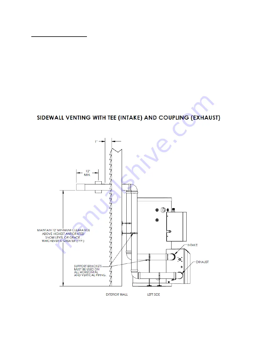
1. DIRECT VENT INSTALLATION OF EXHAUST AND INTAKE
If installing a direct vent option, combustion air must be drawn from the outdoors directly into the
appliance intake, and exhaust must terminate outside. There are three basic direct vent options detailed
in this manual: 1. Side Wall Venting, 2. Roof Venting, and 3. Unbalanced Venting.
Be sure to locate the heater such that the air intake and exhaust vent piping can be routed through the
building and properly terminated. Different vent terminals can be used to simplify and eliminate multiple
penetrations in the building structure (see Optional Equipment in Venting Section). The air intake and
exhaust vent piping lengths, routing and termination methods must all comply with the methods and limits
given in the Venting section, Part 8 of this manual.
When installing a combustion air intake from outdoors, care must be taken to utilize uncontaminated
combustion air.
NOTE: To prevent combustion air contamination, see Table 1.
Figure 18 – LP-314-C - NOTE: This drawing is meant to demonstrate system venting only. The installer is
responsible for all equipment and detailing required by local codes.
Summary of Contents for Versa Hydro PHE130-119
Page 23: ...23 Figure 5 Figure 6 ...
Page 24: ...24 Figure 7 ...
Page 25: ...25 F HYDRONIC PIPING Figure 8 ...
Page 26: ...26 Figure 9 ...
Page 27: ...27 Figure 10 ...
Page 28: ...28 Figure 11 ...
Page 29: ...29 Figure 12 ...
Page 32: ...32 F INTERNAL WIRING Figure 14 Internal connection diagram ...
Page 38: ...38 Figure 17 ...
Page 48: ...48 Figure 25 ...
Page 76: ...76 Figure 29 ...
Page 77: ...77 Figure 30 ...
Page 78: ...78 Figure 31 LP 314 G ...
Page 79: ...79 Figure 32 ...
Page 81: ...81 ...
Page 82: ...82 ...
Page 83: ...83 MAINTENANCE NOTES ...


