


47
2. INDOOR COMBUSTION AIR INSTALLATION IN CONFINED OR UNCONFINED SPACE
This heater requires fresh, uncontaminated air for safe operation and must be installed in a mechanical
room where there is adequate combustion and ventilating air.
NOTE: To prevent combustion air
contamination, see Table 1
on page
Error! Bookmark not defined.
.
Combustion air from the indoor space can be used if
the space has adequate area or when air is
provided through a duct or louver to supply sufficient
combustion air based on the appliance input.
Never
obstruct the supply of combustion air to the
appliance.
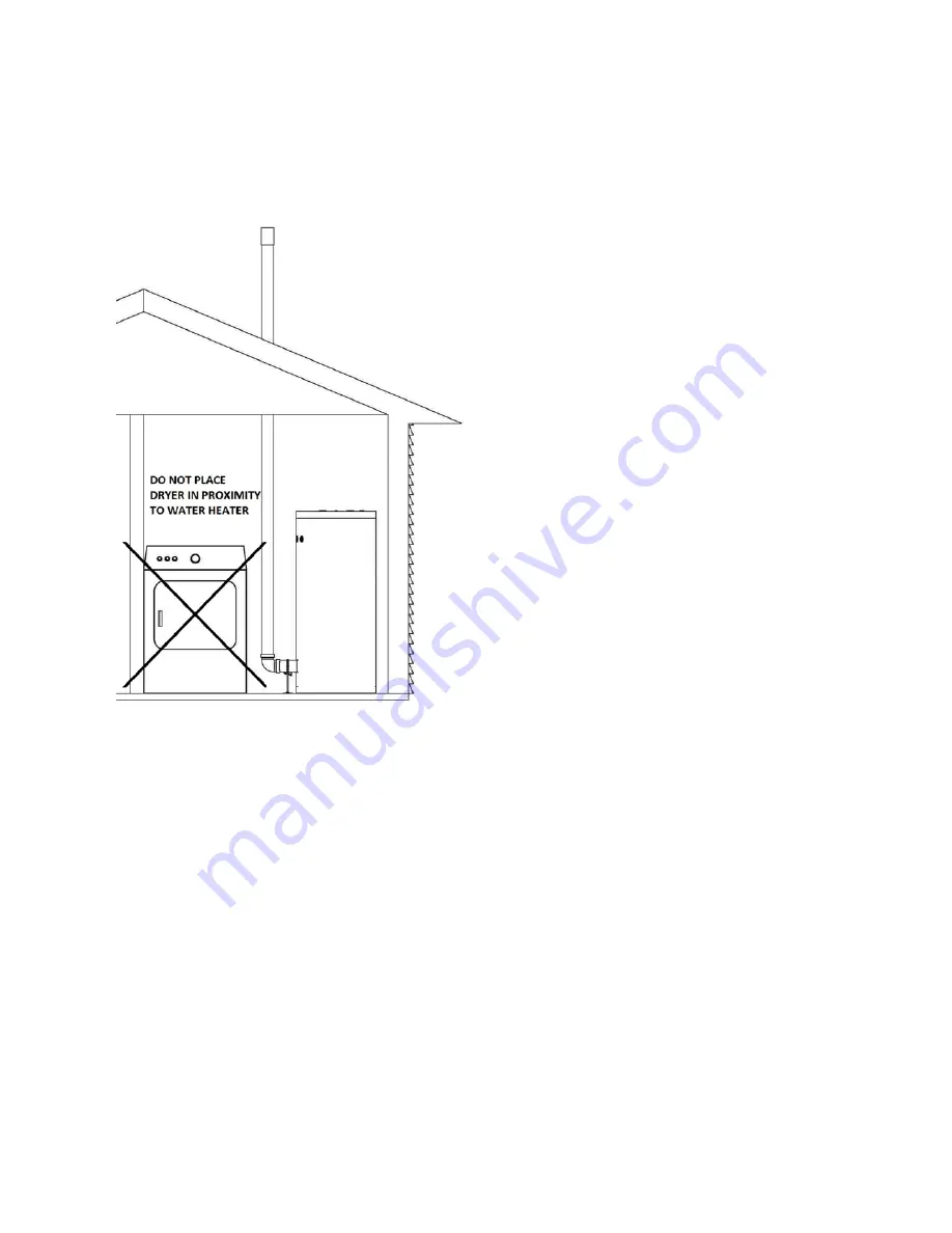
If the appliance is installed in areas
where indoor air is contaminated (see Figure 24) it
is imperative that the appliance be installed as direct
vent so that all combustion air is taken directly from
the outdoors into the appliance intake connection.
Unconfined space
is space with volume greater
than 50 cubic feet per 1,000 Btu/hour (4.8 cubic
meters per kW) of the total input rating of all fuel-
burning appliances installed in that space. Rooms
connected directly to this space, through openings
not furnished with doors, are considered part of the
space.
Confined space
is space with volume less than 50
cubic feet per 1,000 Btu/hour (4.8 cubic meters per
kW) of the total input rating of all fuel-burning
appliances installed in that space. Rooms
connected directly to this space, through openings
not furnished with doors, are considered part of the
space.
When drawing combustion air from inside a
conventionally constructed building to a confined
space, such space should be provided with two permanent openings: one located 6” (15 cm) below the
space ceiling, the other 6” (15cm) above the space floor. Each opening should have a free area of one
square inch per 1,000 Btu/hr (22cm
2
/kW) of the total input of all appliances in the space, but not less than
100 square inches (645cm
2
).
If the confined space is within a building of tight construction, air for combustion must be obtained from
the outdoors as outlined in the Venting section of this manual. See Figure 25
Figure 24 – LP-325-X
Summary of Contents for Versa Hydro PHE130-119
Page 23: ...23 Figure 5 Figure 6 ...
Page 24: ...24 Figure 7 ...
Page 25: ...25 F HYDRONIC PIPING Figure 8 ...
Page 26: ...26 Figure 9 ...
Page 27: ...27 Figure 10 ...
Page 28: ...28 Figure 11 ...
Page 29: ...29 Figure 12 ...
Page 32: ...32 F INTERNAL WIRING Figure 14 Internal connection diagram ...
Page 38: ...38 Figure 17 ...
Page 48: ...48 Figure 25 ...
Page 76: ...76 Figure 29 ...
Page 77: ...77 Figure 30 ...
Page 78: ...78 Figure 31 LP 314 G ...
Page 79: ...79 Figure 32 ...
Page 81: ...81 ...
Page 82: ...82 ...
Page 83: ...83 MAINTENANCE NOTES ...


