|
49
Temperature Switch TS 2-1000
48
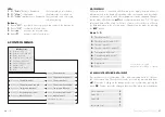
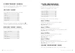
| Input mode „Zirko-Kontroll“ (Controlling the circulation pumps)
T2 Alarm Timer
2
Relay status at malfunction
2
Piezo
+
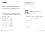
The parameters have the following meanings:
Temperature T1 and T2
In this menu the temperature measured at the sensor T1
and the sensor T2 is displayed.
dT (T1-T2)
In this menu the measured temperature difference
at the sensor T1 and the sensor T2 is displayed.
Interval-Timer
This menu shows the pump interval time value.
lauFzeit Timer
This menu shows the running time of the pump.
T1 min/max
In this menu the highest and lowest measured temperature
at the sensor T1 is displayed.
T2 min/max
In this menu the highest and lowest measured temperature
at the sensor T2 is displayed.
T1 alarm Timer
In this menu the alarm delay time of the sensor T1 is displayed.
T2 alarm Timer
In this menu the alarm delay time of the sensor T2 is displayed.
All other parameters have the same meaning as in the menus mentioned
before. Every menu point can be changed.
11 InpuT mOde “zIrkO-kOnTrOll”
(cOnTrOllIng The cIrculaTIOn pumps)
In this mode the device can be configured as an energy saving controller for a
circulation pump in hot water and heating systems. To do this the temperature sen-
sors are mounted onto the inflow and outflow pipes. The measured temperature
differ ence between inflow and outflow can be used to control a circulation
pump.
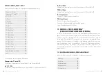
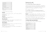
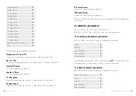
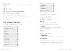
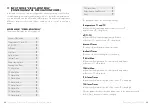
mOde menu “zIrkO-kOnTrOll”
This menu will display the following points:
Name of the mode
,
Temperature T1 and T2
2
dT (T1–T2)
2
Differenz
2
Hysterese
2
Valve interval
2
Interval Timer
2
Pump running time
2
Running time Timer
2
T1 Min./Max.
2
T2 Min./Max.
2
T1 Alarm Min
2
T1 Alarm Max
2
T1 Alarm delay
2
T1 Alarm Timer
2
T2 Alarm Min
2
T2 Alarm Max
2
T2 Alarm delay
2

