3-31
ADJUSTING THE TOE-IN
1. Place the vehicle on a level surface.
2. Measure:
• toe-in
Out of specification
→
Adjust.
Toe-in
0 ~ 10 mm (0.00 ~ 0.39 in)
(with tires touching the ground)
Note
:
Before measuring the toe-in, make sure that the tire
pressure is correct.
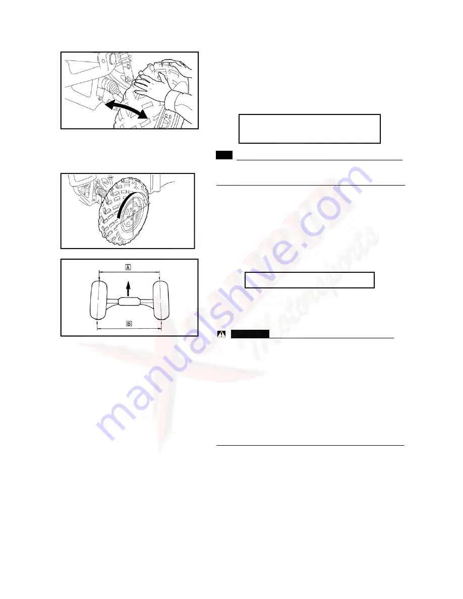
a. Mark both front tire tread centers.
b. Face the steering wheel straight ahead.
c. Measure distance
□
A between the marks.
d. Rotate the front tires 180° until the marks are exactly
opposite one another.
e. Measure distance
□
B between the marks.
f. Calculate the toe-in using the formula given below.
Toe-in=
□
B -
□
A
g. If the toe-in is incorrect, adjust it.
一下。
3. Adjust:
• toe-in
WARNING:
• Be sure that both tie-rods are turned the same
amount. If not, the vehicle will drift right or left even
though the steering wheel is positioned straight.
This may lead to mishandling and an accident.
• After setting the toe-in to specification, run the
vehicle slowly for some distance with both hands
lightly holding the steering wheel and check that the
steering wheel responds correctly. If not, turn either
the right or left tie-rod within the toe-in specification.
a. Mark both tie-rods ends. This reference point will be
needed during adjustment.
b. Loosen the locknut (tie-rod end) on each
①
tie-rod.
c. The same number of turns should be given to both the
right and left tie-rods until the specified toe
②
-in is
obtained. This is to keep the length of the rods the
same.
d. Tighten the rod end locknut on each tie-rod.
Summary of Contents for UTV 700 2009
Page 1: ...HUANSONG UTV 700 SERVICE MANUAL 2009 ...
Page 96: ...GENERAL SPECIFICATIONS 2 23 HYDROGRAPHIC CHART Hydrographic chart Pressure splash ...
Page 97: ...GENERAL SPECIFICATIONS 2 24 LUBRICATION OIL WAY ...
Page 246: ...5 31 BRAKE SYSTEM No Part Name Qty Remarks 26 Caliper piston seal 1 27 Bleed screw 1 ...
Page 330: ...CHARGING SYSTEM 6 18 CHARGING SYSTEM CIRCUIT DIAGRAM Ignition coil C D I Magneto Rectifier ...


