GENERAL INFORMATION
1-20
b. If the adjustment is correct, the 0 mark on the thimble will align exactly with the 0 mark on the
sleeve line. If the marks do not align, the micrometer is out of adjustment.
c. Follow the manufacturer’s instructions to adjust the micrometer.
2B. To check a micrometer larger than 1 in. or 25 mm use the standard gauge supplied by the
manufacturer. A standard gauge is a steel block, disc or rod that is machined to an exact size.
a. Place the standard gauge between the spindle and anvil, and measure its outside diameter or
length. If the micrometer has a ratchet stop, use it to ensure that the proper amount of pressure is
applied.
b. If the adjustment is correct, the 0 mark on the thimble will align exactly with the 0 mark on the
sleeve line. If the marks do not align, the micrometer is out of adjustment.
c. Follow the manufacturer’s instructions to adjust the micrometer.
Care
Micrometers are precision instruments. They must be used and maintained with great care. Note
the following:
1. Store micrometers in protective cases or separate padded drawers in a tool box.
2. When in storage, make sure the spindle and anvil faces do not contact each other or another object.
If they do, temperature changes and corrosion may damage the contact faces.
3. Do not clean a micrometer with compressed air. Dirt forced into the tool will cause wear.
4. Lubricate micrometers with WD-40 to prevent corrosion.
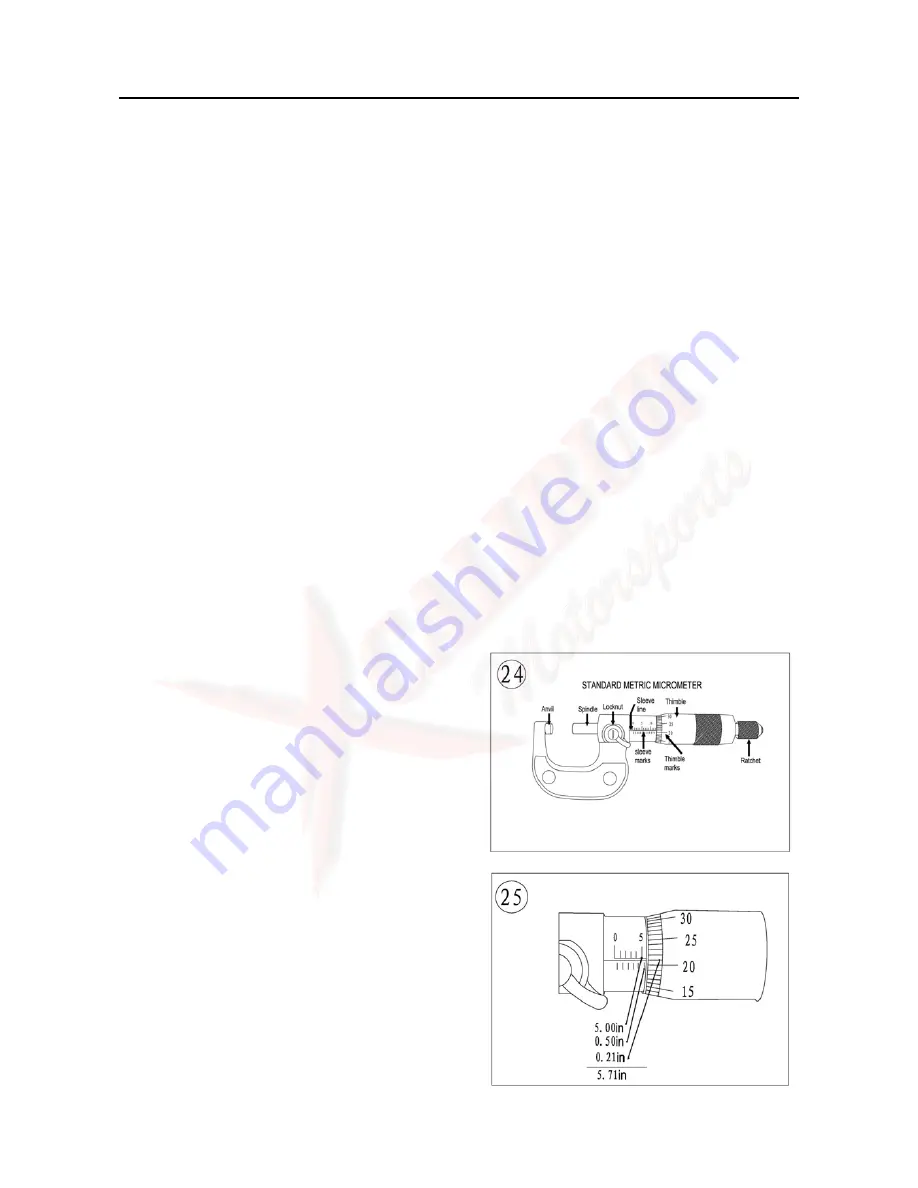
Metric micrometer
The standard metric micrometer (
Figure 24
)
is
accurate to one one-hundredth of a millimeter (0.01
mm). The sleeve line is graduated in millimeter and
half millimeter increments. The marks on the upper
half of the sleeve line equal 1.00 mm. Each fifth mark
above the sleeve line is identified with a number. The
number sequence depends on the size of the
micrometer. A 0-25 mm micrometer, for example, will
have sleeve marks numbered 0 through 25 in 5 mm
increments. This numbering sequence continues with
larger micrometers. On all metric micrometers, each
mark on the lower half of the sleeve equals 0.50 mm.
The tapered end of the thimble has 50 lines
marked around it. Each mark equals 0.01 mm. One
completer turn of the thimble aligns its 0 mark with the
first line lower half of the sleeve line or 0.50mm.
When reading a metric micrometer, add the
number of millimeters and half-millimeters on the
sleeve line to the number of one one-hundredth
millimeters on the thimble. Perform the following steps
while referring to
Figure 25
.
Summary of Contents for UTV 700 2009
Page 1: ...HUANSONG UTV 700 SERVICE MANUAL 2009 ...
Page 96: ...GENERAL SPECIFICATIONS 2 23 HYDROGRAPHIC CHART Hydrographic chart Pressure splash ...
Page 97: ...GENERAL SPECIFICATIONS 2 24 LUBRICATION OIL WAY ...
Page 246: ...5 31 BRAKE SYSTEM No Part Name Qty Remarks 26 Caliper piston seal 1 27 Bleed screw 1 ...
Page 330: ...CHARGING SYSTEM 6 18 CHARGING SYSTEM CIRCUIT DIAGRAM Ignition coil C D I Magneto Rectifier ...


