A-023
HYW3
Series Intelligent Universal Circuit Breaker
A
Primary power distribution
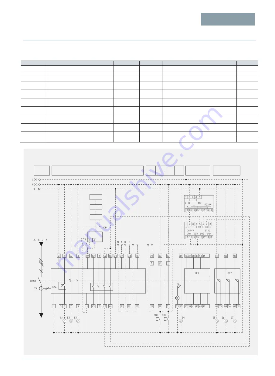
Interpretation of symbols in the wiring diagram
Symbol
Interpretation
Notes
Symbol
Interpretation
Notes
HYW3
HYW3 Series Universal Circuit Breaker
PE
Grounding wire
S1~S7
Signal lamp
User-provided
L(+), N(-)
Control power supply (DC L is positive; N is negative)
TA
Current transformer
A, B, C, N
Main circuit phase line
SAL
Microswitch
DF1
Auxiliary switch
Type
optional
SB1
Opening button
User-provided
DF2
Drawer-mode three-position electric indicator
switch
Optional
accessories
SB2
Closing button
User-provided
ST power
module
Provided with DC 24 V power supply
Optional
accessories
X
Closed electromagnet
ST201
Relay
Optional
accessories
F
Shunt release
Protocol
converter
Except Modbus protocol, other protocols need to
be configured.
Optional
accessories
Q
Undervoltage release
Optional
accessories
M
Electric operating mechanism
SA
Electric operating mechanism limit switch
Main circuit
Intelligent controller
Undervoltage
release
Shunt
release
Closed
electromagnet
Electric
operating
mechanism
Auxiliary switch
Energy
storage
indication
To the
incoming
side of the
circuit
breaker
Draw-out-type three-
position indication
External
transformer
To the
main circuit
See the wiring type of
the auxiliary switch
Connection
position
indication
Test
position
indication
Disconnection
position
indication
Modbus
protocol
Computer
Switchboard
Concentrator
Others
Protocol
converter
Green
Red
ST power
module
Malfunction
indication
Opening
indication
Closing
indication
Wiring diagram of the Secondary Circuit of the Mic5.0 Intelligent Controller


