A-037
HYW3
Series Intelligent Universal Circuit Breaker
A
Primary power distribution
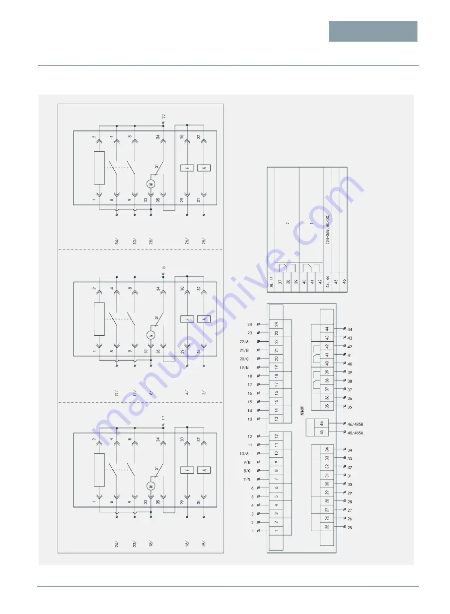
Wiring diagram of the Dual Power Busbar Controller
Pro
g
ra
mma
b
le
re
la
y
Po
w
e
r
s
u
p
p
ly
o
u
tp
u
t
P
o
w
e
r
in
p
u
t
F
e
e
d
b
a
ck
d
e
te
ct
io
n
R
e
s
e
rv
e
d
C
lo
s
in
g
/
o
p
e
n
in
g
P
o
wer
s
u
p
p
ly
output
P
o
w
e
r
in
p
u
t
F
e
e
d
b
a
c
k
d
e
te
c
ti
o
n
C
lo
si
n
g
/
opening
Po
w
e
r
su
p
p
ly
o
u
tp
u
t
R
e
se
rve
d
F
e
e
d
b
a
ck
d
e
te
c
ti
o
n
Com
m
u
n
ic
a
ti
o
n
F
ire
co
n
tro
l
Au
xi
lia
ry
so
u
rce
Control u
nit
Circuit I In
coming
Circuit Brea
ker
Terminal numbe
r
of 1QF
secondary circuit
C
o
m
m
o
n
n
e
u
tr
a
l
w
ir
e
C
lo
si
n
g
o
u
tp
u
t
Dual po
wer wirin
g
terminal panel
O
p
e
n
in
g
o
u
tp
u
t
C
o
mmo
n
live
w
ire
C
lo
si
n
g
d
e
te
ct
io
n
O
p
e
n
in
g
o
u
tp
u
t
T
ri
p
d
e
te
ct
io
n
C
lo
si
n
g
o
u
tp
u
t
O
p
e
n
in
g
o
u
tp
u
t
C
o
mmo
n
live
w
ire
C
lo
si
n
g
d
e
te
ct
io
n
O
p
e
n
in
g
o
u
tp
u
t
T
ri
p
d
e
te
ct
io
n
Note: Th
e gen
er
ator
starting signal co
ntrol
terminals 37, 38
(normally
closed) or 38, 3
9 (normally
open) are wi
red
by users
themselves; and
connected
to th
e auxiliary
power supply
DC
24 V.
Opening
output
C
o
mmo
n
live
w
ire
C
lo
si
n
g
d
e
te
c
ti
o
n
O
p
e
n
in
g
o
u
tp
u
t
T
ri
p
d
e
te
ct
io
n
Control u
nit
II
-way Inco
ming C
ircuit
Break
er
Terminal numbe
r
of 2QF
secondary circuit
Common
neutral
Control u
nit
III
-way (Busb
ar) Ci
rcuit Brea
k
er
Terminal numbe
r
of 3QF
secondary circuit
C
o
m
m
o
n
n
e
u
tr
a
l
w
ir
e
C
lo
si
n
g
o
u
tp
u
t
Supplementary
explanatio
n
Fire signal inp
ut (
default
24
V/AC, DC)
Communicat
ion
485B
Com
m
u
n
icat
io
n
485A
Pro
g
ra
mma
b
le
re
la
y
A
u
x
ili
a
ry
s
o
u
rce
Interpretation of
symbols: 1
QF indicates
C
ircuit I breaker; 2
QF indicate
s Circuit II br
e
aker; 3QF indicat
es bus tie
breaker;
F in
di
cates shunt
rele
ase; X indic
ates closed
el
ectromagnet.
Note: I
, I
I, and III
boxes con
tain the wiri
ng
terminal numbers
of the circu
it breaker s
e
condary circuit, a
nd outside
the box ar
e th
e co
rrespon
ding
termina
l n
umbers
of th
e d
ual p
ower b
usb
ar con
troller
for th
e use
r
wiring. The
three
power su
p
plies are
co
nn
ected
in the
sam
e way.
Important remind
er: To ensur
e the norm
al
operation of the
dual
-powe
r products
and
prevent the
ope
ration errors
, the dua
l
pow
er controllers ne
ed to be
eq
uipped wit
h co
rresponding mec
hanical
int
erlocking d
evic
es.
Controller
Ci
rcu
it
II
C
ircu
it
III
C
ircu
it
I
Au
x
ili
a
ry
R
e
s
e
rv
e
d
C
lo
s
in
g
/
o
p
e
n
in
g


