A-040
HYW3
Series Intelligent Universal Circuit Breaker
C
T
e
rm
in
a
l p
o
w
e
r d
is
tr
ib
u
tio
n
D
In
d
u
s
tr
ia
l c
o
n
tr
o
l a
n
d
p
ro
te
c
ti
o
n
E
p
o
w
e
r
d
e
v
ic
e
A
P
rim
a
ry
p
o
w
e
r
d
is
tr
ib
u
tio
n
B
S
e
c
o
n
d
a
ry
d
is
tr
ib
u
tio
n
A
Primary power distribution
F
G
P
o
w
e
r m
a
n
a
g
e
m
e
n
t
H
ig
h
v
o
lt
a
g
e
c
o
m
p
o
n
e
n
ts
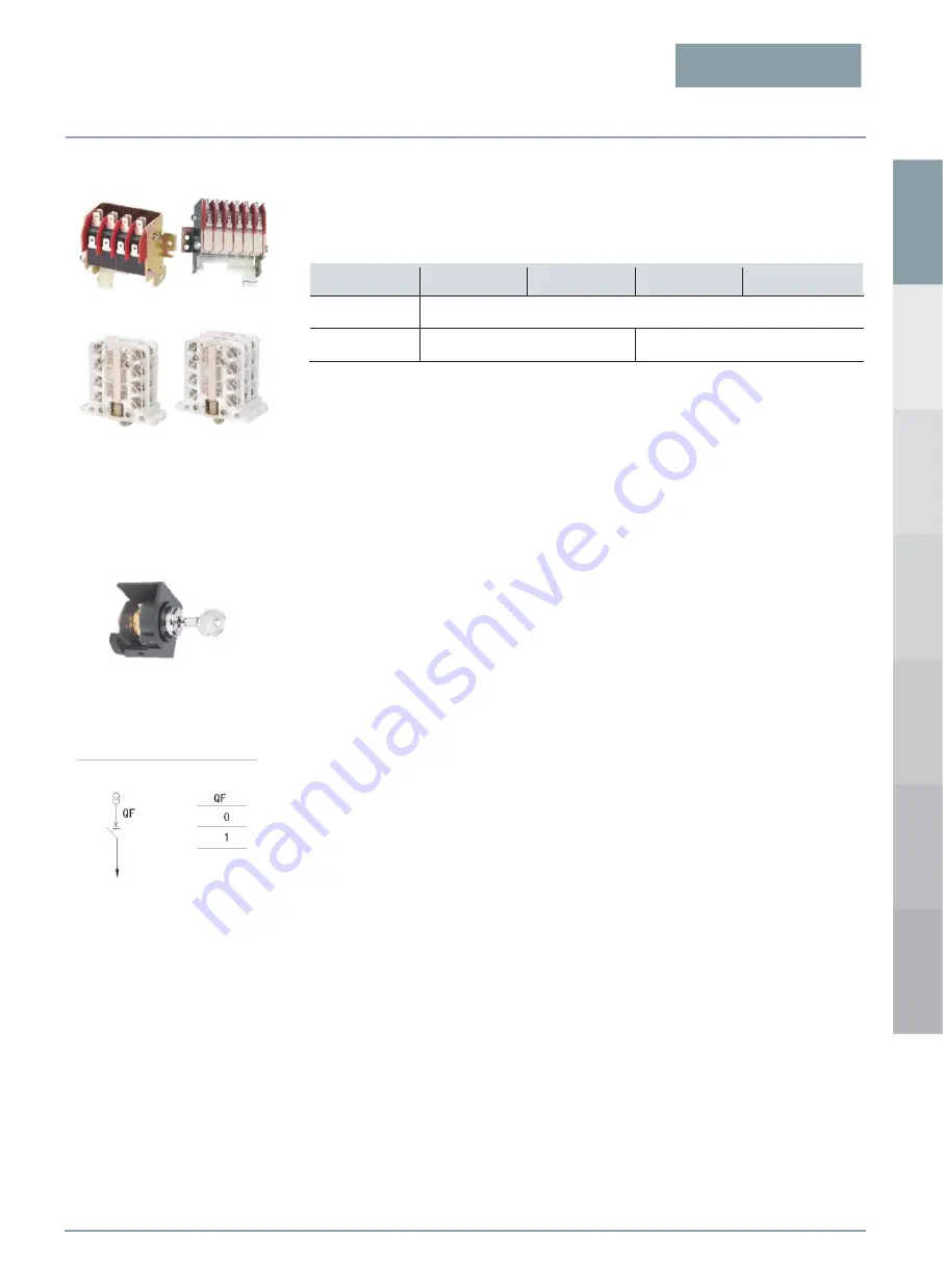
Auxiliary switch
Default configuration: Conversion 4 NO & 4 NC
Other types: Independent four normally open & four normally closed, conversion six normally open
& six normally closed, independent six normally open & six normally closed
Rated working
voltage
AC230V
AC400V
DC220V
DC110V
Arranged thermal
current
6A
Rated control
capacity
300VA
60W
■Key lock
Circuit breaker unlocking: When the notch on the key corresponds to the red dot on the lock, the key
can be inserted into the lock. When the key rotates clockwise to the rightmost
position, it can be unlocked. At this time, the key cannot be directly pulled out, and
the circuit breaker can be closed.
Circuit breaker locking: Press the opening button of the circuit breaker, and then turn the key
counterclockwise to the leftmost position to remove the key. At this time, the
circuit breaker cannot be closed.
Note 1:
The following list of power supply modes is for reference only. The installation and interlock
can be performed according to the needs of the actual power supply system on site, or the
manufacturer can be consulted for negotiation.
One lock and one key: One circuit breaker is equipped with a lock and a key. In the locked state, the
circuit breaker is not allowed to be closed.
Note 1: QF indicates the HYW3 Circuit Breaker; 0 indicates that the circuit breaker is open; 1
indicates that the circuit breaker is closed.
Key lock
Mode I: One Power Supply and
One Load
Circuit diagram
Possible operation
modes
Auxiliary Switch of 1,600
A Shell Frame
Auxiliary Switch of 2,500
A Shell Frame and Above


