background image

WenZhou ZhengBang Electronic Equipment Co., Ltd

ZB4050LS Rev 1.1

9

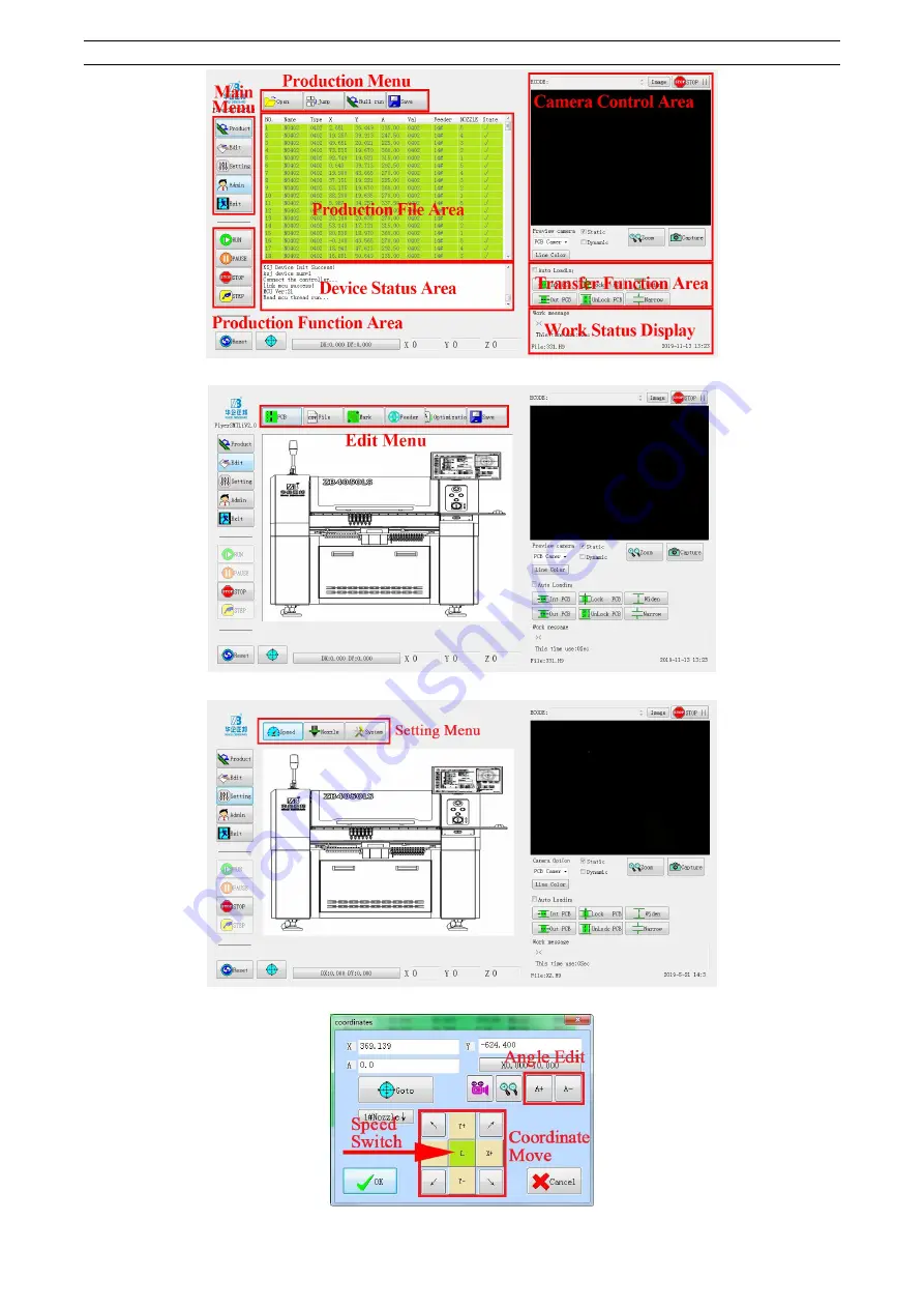
2-7 Menu Composition

Fig. 2-10 Basic Manual

Fig. 2-11 Edit Menu

Fig. 2-12 Setting Menu

Fig. 2-13 Coordinate Edit

Summary of Contents for ZB4050LS

Page 1: ...WenZhou ZhengBang Electronic Equipment Co Ltd ZB4050LS Rev 1 1 ...

Page 2: ...sed by unexpected start up please cut off the power supply before carrying out the maintenance repair and cleaning 5 When unplugging the power plug please hold the plug body instead of the wire and pull out 2 Precautions for application 1 Please take the necessary safety actions during transportation to prevent inversion or falling 2 Please take care of the equipment for shipment 3 Please put the ...

Page 3: ...0 3 3 System Setting 13 Chapter 4 System Edit 14 4 1 How to edit PCB 14 4 2 How to edit file 15 4 3 Mark Edit 23 4 4 Feeder Edit 24 Chapter 5 Production Placement 32 5 1 How to import program 32 5 2 Production Placement 33 5 3 Feed Production 35 5 4 End Turn off the Machine 37 Chapter 6 Maintenance 38 6 1 Daily Maintenance 38 6 2 Weekly Regular Maintenance 38 6 3 Monthly Regular Maintenance 38 6 4...

Page 4: ... 503 5 504 1 505 1 506 1 Set 1 7 LED Alarm Light 3 Kinds of Colors PC 1 8 Handle PC 2 9 Upper and Lower Machine Butted Line 1 5m PC 2 10 IC Tray Fixed Bracket Support 8 Hand Screw 8 PC 1 11 Nozzle Correction Substrate Stainless Steel Substrate PC 1 12 Magnet Round PC 4 13 Check the Nozzle Solid Corrected Nozzle PC 6 14 Inkpad Red PC 1 15 Power Cord 3 1 5 PC 1 16 Toolbox 12 5 PC 1 17 Grease Kunlun ...

Page 5: ...and then fix the alarm to the mounting machine Fig 1 1 Lock Connect Cable Fig 1 2 Lock Screws 4 Display Installation First install the display holder on the mounting machine then fix the display to the holder Fig 1 3 Fix the Holder Fig 1 4 Install Display Screen 5 Keyboard Support Installation Fix the keyboard support to the machine as below shows then place the keyboard and mouse Fig 1 5 Install ...

Page 6: ...trial computer Open and enter the placement machine control system Check the display mouse keyboard etc Fig 1 8 Operating Manual 10 Equipment and Material Preparation Software and Material Use and Tips 1 PCB Design Software PROTEL DXP Etc Download online and install to the machine 2 PCB Source File Convert to the mount coordinate file with Design Software Can directly edit the Source File on the c...

Page 7: ...rsal Casters 7 Keyboard Mouse Tray 8 Emergency Switch 9 Power Indicator 10 Light Switch 11 Computer Switch 12 Main Power Switch 13 USB Port 14 Display Support 15 Rear observation window 16 Chassis Vent 17 Air Switch 18 Power Cord Socket 19 Lan Port 20 Rear Door 21 Y axis Motor Maintenance Window 22 Air Source Processor Fig 2 3 Mainbody Front View Fig 2 4 Mainbody Back View 23 Right SMEMA Port 24 R...

Page 8: ... Linear Guide 9 IC Tray Bracket 10 Adjustable Linear Guide 11 Drop Box 12 Mounting Head Mechanism 13 Rear Feeder Mounting Board 14 X axis Linear Guide 15 Rear Feeder Anti lift Detection Signal Switch 1 Conveyor Belt 2 Guide 3 Load Strip Guide 4 Plywood Cylinder 5 Splint 6 Unload Strip Guide 7 Towline 8 Unload Detection Signal 9 Load Detection Signal 10 Load Conveyor Motor 11 Linear Guide 12 Load w...

Page 9: ...Left right direction Y Up and down direction Unit 0 01mm Displayed as X 000 00mm Y 000 00MM 2 Z axis Height Unit 0 01mm Displayed as Z 00 0mm 3 A axis Rotation angle of mount head Unit 0 1 Displayed as 00 0 Counter clockwise as positive value 2 3 File Type 1 Coordinate File CSV a CSV coordinate file 1 converted and output by PCB source file via DXP and other software 2 Use FlyerSMTLi edit online b...

Page 10: ...011 SMEMA Port X Y Motion Structure Drive Mode Single Arm Direct Connection Drive Type Lead Screw Guide Rail Drive Motor Panasonic Servo Motor Feeder Type Yamaha CL Feeder Specification 8mm 12mm 16mm 24mm 32mm Amount 64pcs Electric Feeder 3pcs Tubular Feeder 3 or 5 IC Tray 2pcs X Y Z Axis X Y axis Move Range 639 656 mm Z axis Move Range 20mm Z axis Effective Range 12mm Z axis Rotation Angle 0 360 ...

Page 11: ...ter Shape Application 502 Φ0 7mm Φ0 4mm 0402 503 Φ1 0mm Φ0 6mm 0402 0603 etc Equivalent Size 504 Φ1 5mm Φ1 0mm 0805 1206 1210 SOT23 etc Equivalent Size 505 Φ3 5mm Φ1 7mm SOP8 SOP14 1812 2220 QFN etc Equivalent Size 506 Φ5 0mm Φ3 2mm QFN TQFP BGA or 22mm 2 6 Substrate Limitation Fig 2 9 Substrate Limitation ...

Page 12: ...WenZhou ZhengBang Electronic Equipment Co Ltd ZB4050LS Rev 1 1 9 2 7 Menu Composition Fig 2 10 Basic Manual Fig 2 11 Edit Menu Fig 2 12 Setting Menu Fig 2 13 Coordinate Edit ...

Page 13: ...ion and PCB Camera Offset 1 Fix the 4 round magnets on the calibration substrate with paper A5 2 Adjust the width of guide rail correction substrate place the substrate on the left side of the guide plate and click Load to send the substrate to the mount position and clamp it 3 Place the inkpad in the middle of the high speed camera Fig 3 2 Inkpad Location NO Name Qty Attention 1 Correction Substr...

Page 14: ...at the mark point Fig 3 3 Nozzle Calibration Fig 3 4 Stick inkpad Fig 3 5 Mark Point 5 Select the nozzle need correct click Confirm to edit Click Position to position the camera to the mark point adjust the coordinate is aligned with the mark point center click Confirm to complete the nozzle correction Fig 3 6 Coordinate Correction 6 Refer to step 5 to complete the other nozzles calibration one by...

Page 15: ...e If failed calibrate it again in the same way Fig 3 7 HD Camera Correction Fig 3 8 Calibration Process Fig 3 9 Correct Result 3 Refer to step 1 to complete other nozzle correction one by one 3 2 3 Nozzle Calibration and High Speed Camera Offset 1 Select the nozzle need calibration click High Speed Camera nozzle starts to automatically correct After finished click View to confirm the coordinates a...

Page 16: ...required for production to save date 6 Conveyor Delay In order to match the speed of the transfer board set the delay time of the stop board When the PCB board reaches the position of the baffle cylinder the baffle cylinder is retracted after the delay time is counted to prevent the PCB board from overshooting and causing the position to stop 7 Conveyor Speed Set the speed of loading and unloading...

Page 17: ... the setting when the PC component is exported Origin usually be set in the bottom left corner Consider cut of the edge accuracy of PCB is not as required it is recommended to select the lower left corner insert via and the MARK or lower left corner component pad is more suitable for the origin 4 1 2Mutiple Board Enter the PCB click Add or Reduce to add the number of boards Select the multi board ...

Page 18: ...tically Attention A few board have flipped 90 or other angles import angle values in the Flip A item 4 2 How to edit file Attention If you have a PCB original file you only need to export the CSV coordinate file and import it into the placement machine You do not need to edit the placement coordinates of the component See 4 2 1 4 2 2 for details If there is no PCB origin file only the component co...

Page 19: ...r left corner component pad as the origin Fig 4 6 Origin Setting Fig 4 7 8 Origin Setting Attention Origin usually be set in the bottom left corner Consider cut of the edge accuracy of PCB is not as required it is recommended to select the lower left corner insert via and the MARK or lower left corner component pad is more suitable for the origin 3 Output File Click on Files assembly output Genera...

Page 20: ...efault 4 2 2 How to import file 1 Install the nozzle Select the appropriate nozzle to install on the patch head according to the quantity of the material 2 set the nozzle according to the installed nozzle click set nozzle to select the corresponding nozzle model Fig 4 11 Set the Nozzle 3 Import Select Edit File to enter the file editing interface click Open File to find the CSV coordinate file con...

Page 21: ... 12 Import File 4 Compensation Angle Deviation Click Confirm File to move the coordinate alignment component center default upper right corner component according to the system prompt to perform angle deviation compensation Fig 4 13 Confirm File Fig 4 14 Confirm Coordinate ...

Page 22: ...orting the CSV coordinate file Otherwise the position may be offset when mounting 6 Component analysis Click the Analyze Components to analyze the file data and display the data in the file list According to the component package setting the model of the mounting nozzle refer to the nozzle type corresponding to the package Fig 4 16 Component Analysis Fig 4 17 Nozzle Edit According to the feeder mo...

Page 23: ...WenZhou ZhengBang Electronic Equipment Co Ltd ZB4050LS Rev 1 1 20 Fig 4 18 Feeder Model Fig 4 19 Feeder Model Fig 4 20 Feeder Model ...

Page 24: ...r settings B Recommend the best feeder installation location C Mentioned which types of nozzles are used Fig 4 21 Material Station Allocation Fig 4 22 Location Recommendation 7 Material Installation Install the component mounted feeder onto the patch according to the station s recommended station installation serial number 8 Optimization Calculate the optimal placement order based on component pic...

Page 25: ...ordinate 2 Edit Basic Parameters Import the component name package value and placement nozzle model Fig 4 25 Edit Basic Parameters 3 Coordinate Edit Double click the X or Y coordinates to pop up the coordinate edit box and move the coordinates to the center of the PCB component pad Import the mounting angle or click A A to adjust the angle click Confirm to save the data and complete the coordinate...

Page 26: ...k Save in the lower right corner to save the latest CSV coordinate file 6 Component Analysis Station Allocation Refer to 4 2 2 steps 3 4 and 5 to complete component analysis and station assignment 4 3 Mark Edit 4 3 1 Mark Position Method Select Edit Mark to enter the identification configuration click Mark1 Edit to pop up the coordinate editing box move the coordinates to Mark1 and click Confirm t...

Page 27: ...k Automatic Identification Offset caused by PCB placement offset PCB edge cutting irregularity Therefore the recognition range should not be too large otherwise the system will not be able to recognize The recommended range does not exceed 1 5 times the outer diameter of Mark and don t appear the similar points in the identification area 4 4 Feeder Edit Type Ribbon Feeder Vibration Feeder Tube IC ...

Page 28: ...eder the above date will be synchronized automatically needn t edit it again 3 Coordinate Correction Click Coordinate to pop up the coordinate editing box click Position to locate the system preset coordinate position then click Single Feed to open the feeder cover adjust the coordinates to align the center position of the component and click Confirm to save the coordinates Fig 4 32 Coordinate Cor...

Page 29: ...ollowing previous instructions 6 Swap Point exchange pop up dialog box enter the feeder serial number to be exchanged and press OK to realize the exchange function of two feeder parameters Fig 4 34 Swap Feeder 7 Re load Re load is only used for the IC tray type component After checking the reload the total number of input components will pop up in the dialog box and then press the OK button to ena...

Page 30: ... type component After checking the reload the total number of input components will pop up in the dialog box and then press the OK button to enable the reload function After the reload is enabled the total number of components will be recounted and the total number will be re loaded Fig 4 36 Feeder Array Fig 4 37 Edit Coordinate ...

Page 31: ...ad is enabled the total number of components will be recounted and the total number will be re loaded Fig 4 38 Activate Tube Feeder 10 Precise Checking the precision identification will enable the high definition camera s precise recognition function The identified components will be corrected multiple times and the placement accuracy will be higher but the efficiency will be reduced It is suitabl...

Page 32: ...fset Fig 4 40 IC Tray Coordinate Editing Diagram 1 Coordinate Adjustment Click Coordinates to move the coordinates to align the first component center in the lower left corner of the tray Fig 4 41 IC Coordinate 2 Number Import Import the total number of pallet components Y direction lines ...

Page 33: ...s to the first component center in the lower right corner of the tray and confirm the saved coordinates Fig 4 43 IC Offset 4 Edit Tray Offset Then move the coordinates to the top right component center in the upper right corner according to the system prompt and confirm the saved coordinates to complete the offset editing Fig 4 44 IC Offset ...

Page 34: ...ent Co Ltd ZB4050LS Rev 1 1 31 4 5 Export Program After editing the parameters click Program in the upper right corner to export the H9Prj program file or you can switch to Production mode to produce the placement Fig 4 45 Export Program ...

Page 35: ...Fig 5 1 Imput Program 2 Match Parameter Automatically generate a production list after importing the program and automatically match the corresponding feeder number and nozzle number No Process Content 1 Boot Turn on the Device and enter system Detail in the boot ready 2 Origin Reset Automatic 3 PCB Load Adjust the rail width and load the PCB 4 Trans Mode Setting Set mode based on requirements Aut...

Page 36: ...Production Normal automatic production placement mode 2 Single step Single step production placement mode 3 Jump Jump to any component as the initial placement position to produce 4 Trial mount Non suction production mode 5 Feed Specified component or feeder feed production 5 2 1 Automatic Production 1 Click Start to recognize and calibrate the mark offset ...

Page 37: ...restart production from the beginning 5 2 2 Single Step Production Single step execution is mainly for machine debugging program calibration troubleshooting etc and each step can be clearly observed 1 Click Single Step to recognize Mark1 and adjust the coordinate correction offset 2 Click single step to recognize Mark2 adjust the coordinate correction offset 3 Step by step single step the system g...

Page 38: ...ode when using jump production and the jump function cannot be used in the independent placement mode 5 2 4 Trial Production Trial Production is mainly for machine warm up and operation training Click the empty the system will automatically start to complete the Mark calibration and not pick up the component placement until the program is installed In the middle you can click the pause and stop to...

Page 39: ...Number 5 Click Start to start the feed production 5 3 2 Specified Component Feeding 1 Switch to Mark Edit mode and select manual identification 2 Return to the production interface and import the production program Click Match to match the related program parameters 3 Click Start enter the Mark point to recognition and calibration status 4 Then click Status in the title to set all components to th...

Page 40: ...n it must be switched to manual identification or converted to the specified feeder mode for feeding production 5 4 End Turn off the Machine 1 Click Exit to exit the placement machine control system 2 Click the Windows Start Menu Turn off 3 Turn off the power switch on the right side of the main unit to cut off the power Attention Before turning off the power be sure to turn off the computer first...

Page 41: ...he transfer mechanism and wipe them with a clean rag 3 Check the Z axis rotating motor shaft and the oil seal contact part for air leakage and add a small amount of white grease 4 Check the X axis linear guide to remove dust and residue and apply new grease 5 Check the X axis ball screw to remove dust and residue and apply new grease 6 Check the Y axis linear guide to remove dust and residue and a...

Page 42: ... of the feeder coordinates 3 Nozzle different suction Check and replace the nozzle 4 Reclaiming time is too short Increase the reclaiming time 5 Insufficient air pressure Increase air pressure Suck Nothing 1 Nozzle doesn t reach component Reset Z axis height 2 Solenoid valve damage Check and replace solenoid valve 3 Vacuum generator damage Check replacement vacuum generator 4 Nozzle blocked Block ...

Page 43: ...coordinates aren t inaccurate Recheck the position and reset feeder coordinate Mounting Angle Error 1 Rotate motor damage Replace the rotating motor 2 Nozzle Mismatch Replace larger size nozzle Sticker doesn t fit 1 The head switch is off Open the sticker switch 2 Plywood placement is not in the mounted state Change to Not mount as placement status 7 5 MARK Point Example Reason Measure Can t catch...

Page 44: ...enance cost and lifetime maintenance as appropriate Revision History Rev Date Rev Page Content 1 0 2019 4 First 1 1 2019 11 1 Add overall route optimization module 2 Add PCB array consolidation 3 Add feeder NO swap module 4 Add tube feeder mode for every location 5 Add IC tray auto reload function 6 Add feeder auto loacting function with array 7 Add cover open slowdown or stop function 8 Add conve...

Page 45: ...42 ...

Reviews: