UPS5000-E-(40 kVA-320 kVA)
User Manual
2 Overview
Issue 10 (2015-09-15)
Huawei Proprietary and Confidential
Copyright © Huawei Technologies Co., Ltd.
22
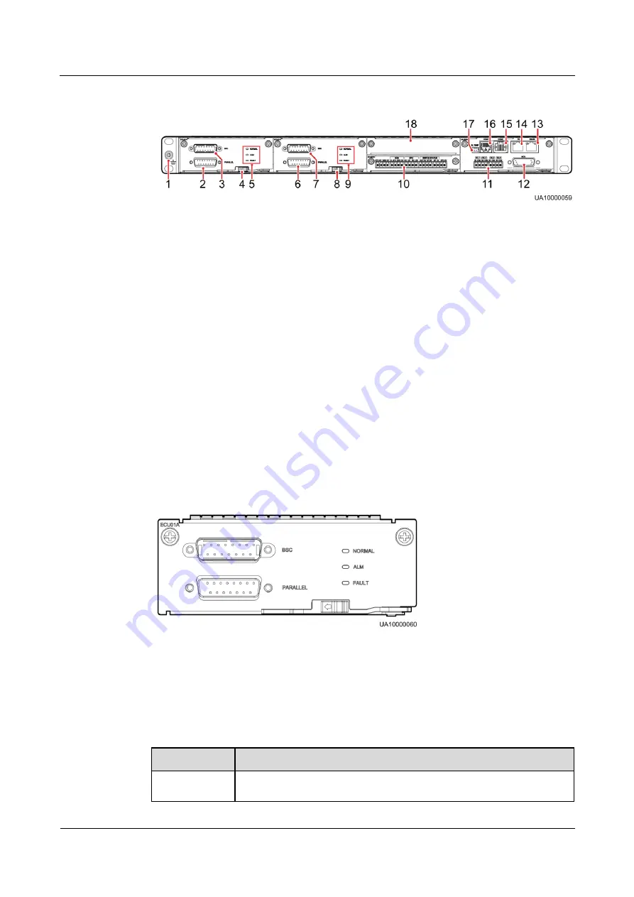
Figure 2-10
CM
(1) Ground terminal
(2) Parallel port 1
(3) BSC port
1
(4) ECM 1 ready
switch
(5) Indicator for ECM 1
(6) Parallel port 2
(7) BSC port
2
(8) ECM 2 ready
switch
(9) Indicator for ECM 2
(10) Dry contact card
(11) Dry
contacts
(12) MDU port
(13) RS485 port
(14) Fast Ethernet (FE)
port
(15) COM2
port
(16) COM1 port
(17) Battery temperature
sensor port
(18) Optional card
subrack cover
2.4.2.2 ECM
The CM provides two active/standby energy control modules (ECMs). Each ECM provides
one BSC port and one parallel port, as shown in
Figure 2-11
ECM
To connect UPSs in parallel, use a parallel cable to connect the parallel ports on the ECMs on
the two UPSs. A hot swappable BSC is used in a dual-bus system to process the
communication information of two UPS systems.
describes the functions of the
ECMs.
Table 2-2
Ports on the ECMs
Silk Screen
Description
PARALLEL
This port transmits parallel signals. To connect UPSs in parallel, use a
parallel cable to connect the parallel ports on the ECMs on the UPSs.
N

