UPS5000-E-(40 kVA-320 kVA)
User Manual
4 User Interface
Issue 10 (2015-09-15)
Huawei Proprietary and Confidential
Copyright © Huawei Technologies Co., Ltd.
118
−
A dual-bus system consists of one master and one slave BSC system, which are
specified by the customer. A BSC system cannot be the master and slave at the same
time. Specify master and slave systems during deployment. To change the setting,
you must follow the guidance of maintenance engineers. Set the master and slave
BSC systems to master and slave BSC modes respectively.
−
Ensure that the BSC signal cable between the master and slave BSC systems is
properly connected and that BSC-related hardware is properly installed.
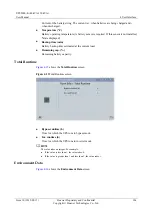
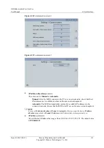
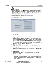
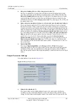
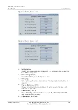
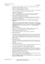
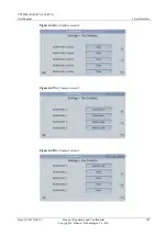
Paral. sys. hibernate
When the customer load is light, set parallel hibernation to alternate modules in
hibernation, which can prolong their service life as well as improving the system
efficiency.
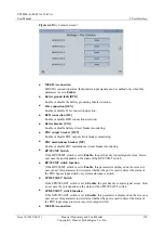
Module cycle hiber. period (d)
0 to 100 days can be set. The parameter
30 days
is set by default.
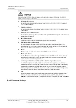
Amb. temp. alarm thresh. (°C)
An alarm is generated when the ambient temperature reaches the preset value.
Top outlet fan
If a top outlet fan is configured, check the fan running status after enabling this
parameter.
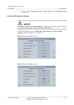
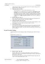
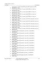
EOD restart
The UPS transfers to battery mode when the mains becomes abnormal. When batteries
reach the EOD threshold and the bypass is disable and
EOD restart
is enable, the UPS
will restart as soon as the mains resumes.
If
EOD restart
is disable, clear the alarm manually or enable the function to restart the
UPS.
EOD restart delay (min)
If
EOD restart
is set to
Enable
, the UPS starts working after
EOD restart delay
when
the mains recovers from an EOD power failure. The value range is 1–1440 min, and the
default value is 10 min.
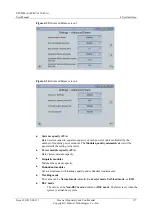
Inverter async. alarm
Specifies whether the
Inverter async.
alarm is displayed when the inverter does not
track the bypass input. The normal power supply is not affected no matter whether you
set the parameter to
Enable
or
Disable
.
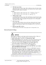
Bus overvoltage recovery
Specifies whether to automatically clear the alarm and restart the power module when
the rectifier or inverter shuts down due to a bus overvoltage alarm. If
Bus overvoltage
recovery
is set to
Enable
, the bus overvoltage alarm is automatically cleared, and the
rectifier and inverter automatically start when the bus voltage recovers (less than 420 V)
within
Bus overvolt.recovery time
. When
Bus overvoltage recovery
is set to
Disable
,
the bus overvoltage alarm cannot be automatically cleared, and the rectifier and inverter
cannot automatically start. The default value is
Enable
.
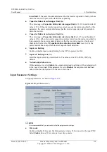
Bus overvolt.recovery time
If
Bus overvoltage recovery
is set to
Enable
, the bus overvoltage alarm is automatically
cleared, and the rectifier and inverter automatically start when the bus voltage recovers
(less than 420 V) within
Bus overvolt.recovery time
. The default value is
5s
.
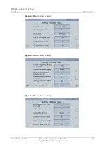
Capacitor failure detection
The default value is
Enable
. When
Capacitor failure detection
is set to
Enable
, the
power module (power unit) performs inverter capacitor fault detection based on the
settings of
Capacitor failure detection upper limit
and
Capacitor failure detection


