UPS5000-E-(40 kVA-320 kVA)
User Manual
4 User Interface
Issue 10 (2015-09-15)
Huawei Proprietary and Confidential
Copyright © Huawei Technologies Co., Ltd.
120
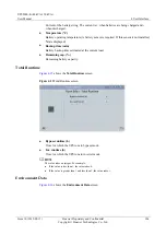
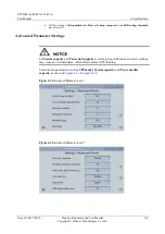
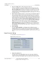
D.G. power limiting (kVA)
and
D.G. charger power ratio (%)
Set these two parameters to control the valid input current and limiting input current,
preventing load impact and facilitating cooperation between the UPS and the D.G. The
D.G. power limiting (kVA)
setting range is 0–5000 kVA. The default value is 150 kVA
for the UPS5000-E-120 kVA, 250 kVA for the UPS5000-E-200 kVA, 400 kVA for the
UPS5000-E-320 kVA. The
D.G. charger power ratio (%)
value range is 0%–100%, and
the default value is 0%.
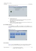
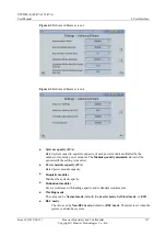
Intra-rack power module start delay (s)
and
Inter-rack power module start delay (s)
The two parameters enable the UPS to control the interval that each rack (or module)
transfers from battery mode to normal mode, which reduces the impact on the generator
or power grid. In the case of battery undervoltage, the system automatically shortens the
delay for transferring to normal mode to 1/8 of the normal delay to accelerate the transfer
and prevent battery overdischarge.
Intra-rack power module start delay (s)
can be set
to a value ranging from 0.5 to 120. The preset value of
Intra-rack power module start
delay (s)
depends on the preset number of power modules. The preset value is 2.0, 1.0,
and 0.5 for 1–5, 6–10, and 10–20 power modules respectively.
Inter-rack power
module start delay (s)
can be set to a value ranging from 2 to 120. The preset value of
Inter-rack power module start delay (s)
is 5.0. The start delay of a module in a rack
varies depending on the rack number and module number. 1# module in rack 1 does not
have a start delay.
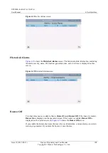
Input adaptability
The value of
Input adaptability
can be
Strong
(default) or
Weak
. Strong input
adaptability applies to the D.G. or input sources whose input current has high frequency
oscillation. In this mode, the total distortion of the input current waveform (THDi) is
poor, but the system is stable. Weak input adaptability is suitable for mains and AC input
sources.
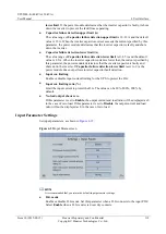
Output Parameter Settings
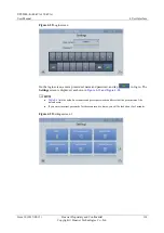
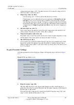
Set output parameters, as shown in
Figure 4-36
Output Param. screen
Output volt. adjustment (V)
The output voltage can be slightly adjusted based on the onsite power distribution
condition to ensure a minimum difference between the output voltage and the bypass
voltage. This facilitates uninterruptible transfer from normal mode to bypass mode. The

