18
No.
Check Item
Check Result
3
Unused ports (such as RF1, RF2, Ethernet optical port, and
Ethernet electrical port) are protected by dustproof plugs.
□
Passed
□
Failed
4
Routing for the power cable and signal cable meets the
requirements for routing strong-current and weak-current cables
and complies with the cable routing plan.
□
Passed
□
Failed
5
Cables are bound neatly, and cable ties are secured evenly and
properly in the same direction.
□
Passed
□
Failed
6
There is no unnecessary adhesive tape or cable tie on cables.
□
Passed
□
Failed
12
Powering On the System
Power-on Procedure
12.1
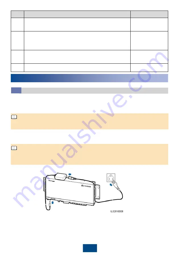
1. Insert the output terminal of the power adapter into the
12V IN
port of the SmartLogger.
2. Insert the power cable into the power adapter.
3. Insert the power cable plug into an AC socket.
1. The rated input of the power adapter is 100
–240 V AC, 50 Hz or 60 Hz.
2. Select an AC socket that matches the power adapter.
4. Switch on the circuit breaker of the AC socket.
5. Switch on the upstream circuit breaker of the AC power cable.
1. Step 5 needs to be performed only in the PLC (MBUS) networking scenario.
2. In a scenario without a smart array controller, place the power adapter on the top of the
SmartLogger and secure the power adapter using a cable tie.
NOTE
NOTE


