background image


Installing Cables

b

c

d

e

f

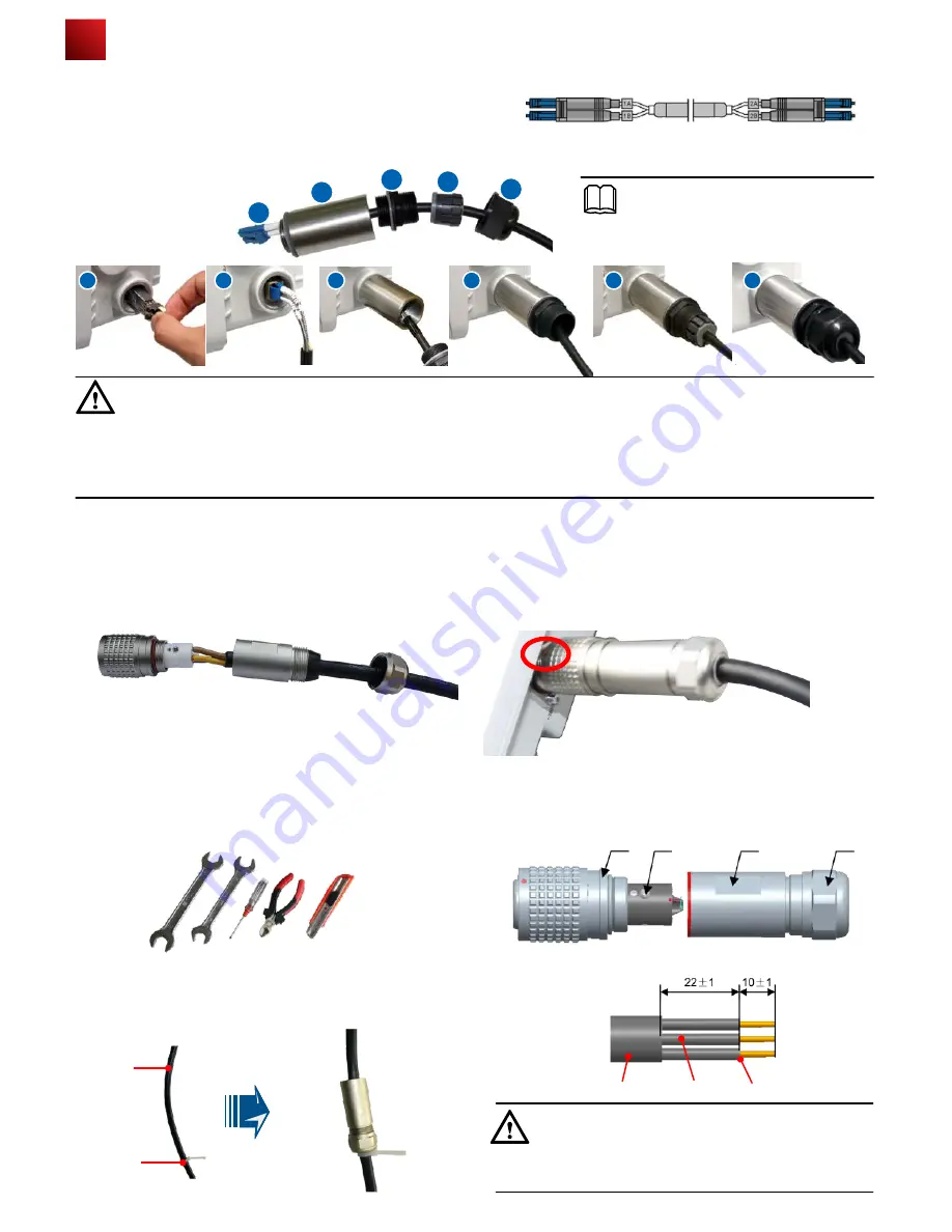
2.  The optical fiber connection of AP6610DN-AGN-US is similar to that of WA653SN. Here, WA653SN is used as an 
example. Connect the optical fiber to the AP and ensure that the waterproof connector is fastened.

CAUTION

● 

Connecting optical fibers

   1.  The right figure shows the appearance of the optical fiber

The thread must be secured properly; otherwise, optical fibers may be damaged. When removing optical fibers, remove the
waterproof PG connector, and then remove the optical fiber


 connected to the AP. When removing the waterproof PG 

connector, use the ejector lever to clutch the optical fiber tube. This prevents the optical fiber tube from rotating with the 
waterproof PG connector and protects optical fibers.

7

NOTE

Install an optical module as shown in step a
before connecting the fiber.

a

b

c

d

e

f

Figure 2

Figure 1

● 

Connecting AC power cables

   1.   Make an AC power cable onsite, cut the cable of proper length. Make a cable according to figure 1. L/N/PE pin 
         arrangement must be correct.
   2.  When connecting the AC power cable to the AP, align the socket to the red point of the connector, and insert the
         waterproof connector. When a crack sound is heard, the AC power cable is installed properly. When removing the AC
         power cable, press the  component with the red point. You do not need loosen the screw.

● 

Making AC Power Cables Onsite 

a  Preparation

1.  The required tools are as follows: open-end wrench
(22mmX24mm), open-end wrench (22mmX24mm), Phillips
screwdriver (0#X50mm), diagonal pliers, and utility knife.

Nut

Socket

Screw

Shell

CAUTION

b  Connection 

1.   Use cable ties to fasten the cable, remove the socket 
and nut together, and then lead the cable through the socket 
and nut.

Cable tie

Wiring 

terminal

Cable

Be careful when striping the cable, please don't damage
the Core wire and the Conductor.

2.  Strip the cable.

Core wire Conductor

2.  The following table shows the connector components.

Summary of Contents for AP6610DN-AGN-US

Page 1: ...AP6610DN AGN US Outdoor Wireless LAN Access Point Quick Start Guide HUAWEI TECHNOLOGIES CO LTD ...

Page 2: ...vices and features described in this document may not be within the purchase scope or the usage scope Unless otherwise specified in the contract all statements information and recommendations in this document are provided AS IS without warranties guarantees or representations of any kind either express or implied The information in this document is subject to change without notice Every effort has...

Page 3: ...ed could result in equipment damage data loss performance degradation or unexpected results Provides additional information to emphasize or supplement important points of the main text 2 Change History Changes between document issues are cumulative Therefore the latest document issue contains all the changes in previous issues Change in Issue 01 2012 09 30 Initial commercial release ...

Page 4: ...o fiber An optical module is required Used for Ethernet connections Connected to an AC power module Connected to the feeder Connected to the feeder 5 2 Expansion bolt PCS 6 2 M4X12 hexagon socket head cap screw PCS Press and hold down the Reset button for 3 seconds to restore the factory settings and restart the AP 7 Item Description No Product functions 10 11 1 1 Item Quantity Unit PCS PCS Warran...

Page 5: ...lation position and use the marker level and measuring tape to mark the drilling positions where expansion bolts are installed 2 Use 8 drill bit to drill 35 mm to 40 mm deep holes in the drilling positions and install expansion bolts Screw the nut into the expansion tube hammer the expansion bolt into a hole until the flat washer is flattened against the wall and remove the nuts spring washer and ...

Page 6: ...on the hoop 2 Slide the AP that has the connector fastened into the wall mounting bracket The procedure for installing the AP6610DN AGN US against a horizontal pole is similar to the procedure for installing the AP6610DN AGN US against a vertical pole Installing the Security Lock To prevent unauthorized personnel from moving the AP lock the AP The preceding figure shows the security lock The carri...

Page 7: ...ensure that it is connected to a ground cable a Waterproof adhesive tape Ground cable NOTE Surge protection device c b Waterproof adhesive tape Feed line Feed line When no antenna is installed on the 5G antenna interface cover the interface with a dustproof cap and wrap the dustproof cap with insulating tape and waterproof tape Wrap the feed line using one layer PVC black insulation tape three lay...

Page 8: ...onnecting AC power cables 1 Make an AC power cable onsite cut the cable of proper length Make a cable according to figure 1 L N PE pin arrangement must be correct 2 When connecting the AC power cable to the AP align the socket to the red point of the connector and insert the waterproof connector When a crack sound is heard the AC power cable is installed properly When removing the AC power cable p...

Page 9: ...components Connector jacks can t be short circuited Connections between the metal shell and the connector jacks can t be short circuited Cable core wires are connected properly to the corresponding connector jacks d Protection The device is placed outdoors warp up the connector using three layers of PVC insulation tapes to prevent it from being damaged as shown in the following figure CAUTION Each...

Page 10: ... the shielded cable should have good electric contact with the metal shell of the equipment they connect to 4 Ground cables must be separated from signal cables to reduce interference between them 5 Do not add any switch or fuse on the ground cable 6 Do not use another device for an electrical connection with the ground cable 7 All metal components in the shell must be securely connected to the gr...

Page 11: ...e packets are being transmitted Off The system is working properly the Ethernet is connected and radios are disabled The indicator blinks more quickly when more data is being transmitted Blinking yellow The system is working properly but the Ethernet is not connected The AP has wireless users connected to the 5 GHz band and is transmiting data The indicator blinks more quickly when more packets ar...

Page 12: ...the ping 192 168 0 1 command on the PC to check whether the PC can be pinged If the ping operation succeeds the connection is set up successfully If the ping operation fails The connection fails to be set up Check whether the network cable works properly Step 3 Access the command line window on the PC For example if the PC runs Windows XP choose Start Run and enter cmd in the displayed dialog box ...

Page 13: ...he hazardous substance contained in all the homogeneous materials of this part is above the limit requirement Hazardous Substances Pb Hg Cd Cr6 PBB PBDE Part Mechanical part Board circuit module Signal cable Cable connector Power adapter Auxiliary equipment O O O O O O O O O O O O O O O O O O O O O O O O O O O O O O Declaration on Hazardous Substances in Electronic Information Products QUALIFICATI...

Page 14: ...sed by improper handling in transportation and assembly 2 The defects are caused by the fact that the product is dismantled or altered by anyone that is not from a Huawei authorized service partner 3 The defects are caused by the fact that the product is used in a harsh environment that is not suitable for the operation of the product 4 The defects are caused by any force majeure including but not...

Page 15: ...HUAWEI TECHNOLOGIES CO LTD Huawei Industrial Base Bantian Longgang Shenzhen 518129 People s Republic of China Http enterprise huawei com ...

Reviews: