background image

LTE CPE B2368 User's 
Guide 

2 Introduction to Web configuration interface 

Issue 01 

Copyright © Huawei Technologies Co., Ltd. 

16 

2.1.2 Access to the web-based configuration interface 

Step 1

 Ensure that all parts are properly connected LTE modem (for more information see 

Step 1

 Ensure that all parts are properly connected LTE modem (for more information see 

Quick Start Guide). 

step 2

 Start your Internet browser. 

step 2

 Start your Internet browser. 

step 3

 In the address bar, type " 192.168.1.1 ".

step 3

 In the address bar, type " 192.168.1.1 ".

step 3

 In the address bar, type " 192.168.1.1 ".

step 3

 In the address bar, type " 192.168.1.1 ".

step 3

 In the address bar, type " 192.168.1.1 ".

step 4

 You will be prompted to enter a user name and password. 

step 4

 You will be prompted to enter a user name and password. 

If you want to enter the configuration interface to access user to enter a user name "

 user

 ". The 

If you want to enter the configuration interface to access user to enter a user name "

 user

 ". The 

If you want to enter the configuration interface to access user to enter a user name "

 user

 ". The 

If you want to enter the configuration interface to access user to enter a user name "

 user

 ". The 

password can be found on a label on the back of the modem.

Click on 

Login.

 If you have already changed the default password, then enter your chosen password and click 

Login.

Click on 

Login.

 If you have already changed the default password, then enter your chosen password and click 

Login.

Click on 

Login.

 If you have already changed the default password, then enter your chosen password and click 

Login.

Click on 

Login.

 If you have already changed the default password, then enter your chosen password and click 

Login.

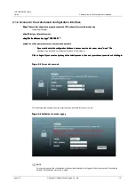
Figure 2-5

 Screen with password 

Figure 2-5

 Screen with password 

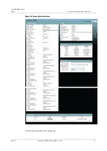
The following screen appears when you enter the wrong password three times in a row. 

Figure 2-6

 Notification of blocked logging 

Figure 2-6

 Notification of blocked logging 

NOTE 

For security reasons, the configuration interface will automatically be logged off after five minutes of inactivity (by 
default). If this happens, simply log in again.

Summary of Contents for B2368

Page 1: ...LTE CPE B2368 User Manual Date 03 31 2018 HUAWEI TECHNOLOGIES CO LTD ...

Page 2: ...nd the customer No products or parts services or features discussed in this document may not be within the scope of the purchased product or method of use Unless otherwise specified in the contract all data information and recommendations in this document are provided as are given without warranty or representation of any kind whether express or implied The information contained in this document i...

Page 3: ...t Purpose Equipment means LTE Long Term Evolution modem Acronym ODU expresses the outdoor unit while acronym IDU indoor unit The LTE modem is a complete security solution simultaneously containing reliable firewall operating on the principle stateful packet inspection SPI and denial of service Denial of Service DoS ...

Page 4: ...utdoor unit 9 1 5 2 Indoor unit 10 1 5 3 RESET button 12 2 Introduction to Web configuration interface 13 2 1 Overview 13 2 1 1 For the basic settings 13 2 1 2 Access to Web configuration interface 16 2 2 Layout configuration interface 17 2 2 1 Top Panel 18 2 2 2 Main window 18 2 2 3 User account 18 2 2 4 Navigation Panel 18 3 connection status and system information 19 3 1 Overview 19 3 2 Status ...

Page 5: ...ting using WiFi Protected Setup WPS 49 6 Setting up a home network 54 6 1 Overview 54 6 1 1 What You Need to Know 54 6 2 LAN Settings screen 55 6 3 Static DHCP screen 58 6 3 1 Before 58 6 4 UPnP screen 60 6 5 Screen UPnP list 60 Static routing 7 62 7 1 Overview 62 7 2 Configuration of static routing 63 7 2 1 Add Edit Static Routing 64 8 Network Address Translation NAT 66 8 1 Overview 66 8 1 1 What...

Page 6: ...ecurity firewall 85 10 6 2 Other safety tips 85 11 MAC address filter 86 11 1 Overview 86 11 1 1 What You Need to Know 86 11 2 Screen MAC address filter 86 12 Parental 89 12 1 Overview 89 12 2 Screen Parental 89 12 2 1 Add New Edit PCP 90 13 L2TP VPN 93 13 1 Overview 93 13 2 Settings screen 93 13 2 1 Screen Add new tunnel tunnel Modification 94 13 3 Screen Monitor 96 4 13 Configuration Example L2T...

Page 7: ...1 System 17 logs 132 17 1 Overview 132 17 1 1 What You Need to Know 132 17 2 System Log Screen 133 17 3 Screen Recording calls 134 17 4 Screen History VoIP calls 135 User account 18 136 18 1 Overview 136 18 2 Screen User Account 136 19 System 138 19 1 Overview 138 19 1 1 What You Need to Know 138 The 19 2 screen 138 19 3 Screen encryption key 139 19 3 1 Common usage Set of indoor and outdoor unit ...

Page 8: ...ine update process 154 24 Backup Restore 162 24 1 Overview 162 Screen 24 2 Backup Restore 162 25 reboot screen 165 26 Diagnosis 166 26 1 Overview 166 Screen 26 2 Ping TraceRoute 166 27 Troubleshooting 168 27 1 Overview 168 27 2 Power hardware connections LED indicators 168 27 3 LTE modem configuration interface and log 168 27 4 Internet access 170 27 5 Wireless Internet access 170 27 6 Telephone c...

Page 9: ... Figure 1 1 computers can be connected directly to the port ETHERNET LTE modem or wirelessly via Wi Fi Figure 1 1 computers can be connected directly to the port ETHERNET LTE modem or wirelessly via Wi Fi Figure 1 1 computers can be connected directly to the port ETHERNET LTE modem or wirelessly via Wi Fi Figure 1 1 computers can be connected directly to the port ETHERNET LTE modem or wirelessly v...

Page 10: ... network is active the LTE modem to connect devices that support IEEE protocols 802 11b g n ac and have access to network resources You can configure the wireless network using WPS Wi Fi Protected Setup or client device to manually add the network Figure 1 3 Diagram Wireless Figure 1 3 Diagram Wireless 1 2 WLAN Button Press WPS on the back of the modem internal unit can wireless 2 4 GHz and 5 GHz ...

Page 11: ... range of the LTE modem LED indicator WLAN WPS LTE devices supporting this technology which is in range of the LTE modem LED indicator WLAN WPS LTE modem when connecting to another device via WPS flash End NOTE WPS function on LTE modem and the connected wireless devices must be activated within a time span of more than two minutes For more information see 5 4 WPS screen 1 3 Methods for Administra...

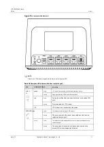
Page 12: ...nector to connect the input connector PoE indoor unit Third LED Third LED Table 1 1 LED indicators outdoor unit Table 1 1 LED indicators outdoor unit Color Behavior State Off The device is off red steady on There is a fault no jack in the SIM card Flashing being updated green Flashing is starting steady on Powerful LTE Signal SINR 10 db Powerful LTE Signal SINR 10 db Powerful LTE Signal SINR 10 db...

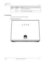
Page 13: ...Color Behavior State Orange steady on Weak LTE signal SINR 4 db Flashing No LTE signal search or disconnected 1 5 2 Indoor unit The following picture is a diagram LED indicators and their labels Figure 1 5 The front panel of the indoor unit Figure 1 5 The front panel of the indoor unit ...

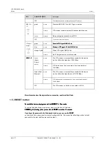
Page 14: ...n Shines LTE modem is connected to the network and ready for use Flashing Ongoing marketing LTE modem into operation red Shines During the self test fault has been detected not inserted SIM card Flashing Firmware update is LTE modem Off LTE modem is not connected to the mains PHONE Green Shines The telephone jack is assigned SIP account Flashing Phone connected to the socket has posted handset dev...

Page 15: ...ps Flashing LTE device sends receives data to from the network speed of 10 100 Mbps Off The LTE modem no device is connected via LAN More information about the physical device connection see Quick Start Guide More information about the physical device connection see Quick Start Guide 1 5 3 RESET button To restart the device simply press and hold RESET 3 10 seconds To restart the device simply pres...

Page 16: ...er Third Opera 36 and higher 4th Safari 10 1 2 and higher 5th Internet Explorer 11 0 and higher on Windows 7 and later The recommended screen resolution is 1366 x 768 pixels In order to use configuration interface is needed to enable or activate the following Popups internet browser you are using By default browser in Windows 7 is active popup blocker JavaScript enabled by default Permission to ac...

Page 17: ...connection status Figure 2 2 connection status step 4 mouse to select Internet Protocol Version 4 TCP IPv4 and then click on Properties step 4 mouse to select Internet Protocol Version 4 TCP IPv4 and then click on Properties step 4 mouse to select Internet Protocol Version 4 TCP IPv4 and then click on Properties step 4 mouse to select Internet Protocol Version 4 TCP IPv4 and then click on Properti...

Page 18: ...oose Obtain an IP address from a DHCP server and Obtain DNS server address automatically and click on OK then Close and in the next window again Close automatically and click on OK then Close and in the next window again Close automatically and click on OK then Close and in the next window again Close automatically and click on OK then Close and in the next window again Close automatically and cli...

Page 19: ... user to enter a user name user The If you want to enter the configuration interface to access user to enter a user name user The If you want to enter the configuration interface to access user to enter a user name user The password can be found on a label on the back of the modem Click on Login If you have already changed the default password then enter your chosen password and click Login Click ...

Page 20: ... prompting you to change your password step 6 The default screen Connection status step 6 The default screen Connection status step 6 The default screen Connection status step 6 The default screen Connection status Figure 2 8 connection status Figure 2 8 connection status step 7 Click on the link System Information go to the same screen that offers step 7 Click on the link System Information go to...

Page 21: ... Section 3 3 System Information screen about the system screen System Information is further discussed in Section 3 3 System Information screen about the system screen System Information is further discussed in Section 3 3 System Information screen If you click on LAN equipment on the screen System Information A in Figure 2 9 screen displays Connection If you click on LAN equipment on the screen S...

Page 22: ...nd an overview of SIP accounts You can also register and unregister individual SIP accounts 3 2 Status Screen Connection This screen provides an overview of network status information about the modem and the various connected devices If there is a problem in the network connection is displayed on the screen warning message Figure 3 1 Connection status Display Mode icons Figure 3 1 Connection statu...

Page 23: ... You can see detailed information about the client device by clicking on its icon and then on the link Information then on the link Information Figure 3 3 Connection status Display Mode List About Figure 3 3 Connection status Display Mode List About Figure 3 3 Connection status Display Mode List About Figure 3 3 Connection status Display Mode List About At display mode list you ll see information ...

Page 24: ...ide 3 connection status and system information Issue 01 Copyright Huawei Technologies Co Ltd 21 Figure 3 4 Screen System Information Figure 3 4 Screen System Information Individual fields are described in the following table ...

Page 25: ...enu Device installed on the device The firmware can be updated via the menu Device Management Software Upgrade hardware version This field shows the hardware version of your device WAN information Regime This is the method of encapsulation used by your ISP IP address This field is the current IP address LTE modem WAN WAN 2 Information Regime This is the method of encapsulation used by your ISP IP ...

Page 26: ...ive if the appropriate security settings for the wireless network state radio On appears every time the radio antenna WLAN active disabled appears every On appears every time the radio antenna WLAN active disabled appears every On appears every time the radio antenna WLAN active disabled appears every On appears every time the radio antenna WLAN active disabled appears every time the radio antenna...

Page 27: ...he LTE modem is connected to the LTE network Disconnected Otherwise ie when the LTE network is not available For network Disconnected Otherwise ie when the LTE network is not available For network Disconnected Otherwise ie when the LTE network is not available For the LAN interface is specified in this field connected if the LTE modem uses this the LAN interface is specified in this field connecte...

Page 28: ... unregister to deregister an account SIP to SIP server This action will Click on unregister to deregister an account SIP to SIP server This action will not lead to the removal of your SIP account simply cancel your SIP identity mapping to appropriate IP address or domain name In the second field will be displayed Registered In the second field will be displayed Registered If the SIP account is not...

Page 29: ...m information Issue 01 Copyright Huawei Technologies Co Ltd 26 Item Description URI In this field the account number and account SIP service domain The values can be changed through the menu VoIP SIP SIP account changed through the menu VoIP SIP SIP account ...

Page 30: ...ettings in this section you can set various connection parameters eg To enter the PIN code of the SIM card lock specific band frequency transmitter or LTE networks 4 2 Display Broadband Using this screen you can lock specific band frequency transmitter or LTE networks Enter this screen by clicking on Network Settings Broadband clicking on Network Settings Broadband Figure 4 1 Network Settings Broa...

Page 31: ...t want to LTE modem to connect to the LTE network of other Choose Prohibit if you do not want to LTE modem to connect to the LTE network of other Choose Prohibit if you do not want to LTE modem to connect to the LTE network of other operators Use Click to save the changes made in this section Cancel Click to restore previous settings in this section internet settings Serial number of broadband in ...

Page 32: ...AN interface enable NAT Check to NAT routing for the WAN interface IP Pass Through Check this box to allow access providers assign IP directly addresses devices on the LAN This setting disables possibly setting NAT and DHCP server configuration Network Settings Home Network LAN Settings LTE DHCP server configuration Network Settings Home Network LAN Settings LTE DHCP server configuration Network S...

Page 33: ...Network Settings Broadband SIM Table 4 3 Network Settings Broadband SIM Item Description SIM Status This field displays the status of the SIM card in the system PIN off The SIM card is not protected by a PIN PIN off The SIM card is not protected by a PIN PIN off The SIM card is not protected by a PIN PIN required The SIM card is protected by a PIN code which has not yet been specified PIN required...

Page 34: ...M card is not required to enter a PIN enter PIN If authentication is enabled PIN enter in this field 4 digit PIN eg 0000 that you received from your service provider In the event that your PIN is entered incorrectly too often it can be blocked SIM card which will then be used to access the Internet The remaining experiments The remaining number of attempts to enter the correct PIN before locking t...

Page 35: ...oo often you This field displays the status of the SIM card in the system PIN locked Too often you entered the wrong PIN and the SIM card was therefore locked To unlock and use a SIM card you will need the PUK code which is available from your operator PUCK Enter the PUK Pin Unlock Key you received from your operator to unlock the SIM card new PIN Enter a new PIN SIM card Confirm new PIN Repeatedl...

Page 36: ...nt devices ie Increasing the reach of your wireless network Typically there are two types of wireless networks Type infrastructure which is a part of one or more access points and several wireless client devices Type infrastructure which is a part of one or more access points and several wireless client devices Type infrastructure which is a part of one or more access points and several wireless c...

Page 37: ...work is governed by the following basic rules All devices on the wireless network must use the same SSID SSID is the name of the wireless network It is an abbreviation of the English phrase Service Set Identifier ie the identifier of the wireless network If there are two overlapping wireless networks should each transmit on a different channel Like radio stations and television channels used by ea...

Page 38: ...PS and some that are not you can use WPS for network and device settings without the support WPS her then manually add though the process is somewhat more complicated I want to set advanced network parameters If so which If you want to make advanced settings of the wireless network make sure that you know exactly what you are doing Otherwise ignore the advanced settings NOTE The following chapters...

Page 39: ...LTE CPE B2368 User s Guide 5 Wireless WiFi 2 4 5 GHz Issue 01 Copyright Huawei Technologies Co Ltd 36 Figure 5 2 Network Settings WiFi 2 4 GHz General Figure 5 2 Network Settings WiFi 2 4 GHz General ...

Page 40: ...twork enable the checkbox Enable WiFi Wireless network enable the checkbox Enable WiFi Setting up a wireless network Wireless network name SSID The name of the wireless network s SSID Service Set Identity is used as an identifier for the wireless client devices Wireless devices that use the Access Point AP must use the same SSID Enter a descriptive name up to 32 characters without diacritics wirel...

Page 41: ... n c allows any device that supports IEEE 802 11a IEEE 802 11n 802 11a n c allows any device that supports IEEE 802 11a IEEE 802 11n IEEE 802 11ac 802 11an ac allows connection of all devices that support IEEE 802 11n 802 11an ac allows connection of all devices that support IEEE 802 11n IEEE 802 11ac 802 11a nn allows connection of all devices that support IEEE 802 11 802 11a nn allows connection...

Page 42: ...select No security In this case this wireless screen next setting You can also select No security In this case this wireless network will be able to connect any device without any data encryption or authentication More information about individual security modes summarized in the following chapters Use Click on Use to save your changes settings LTE modem Click on Use to save your changes settings ...

Page 43: ...PA 2 PSK Figure 5 5 Figure 1 1 WiFi 2 4GHz 5GHz WiFi General Increased safety WPA 2 PSK The following table summarizes the available fields on this screen Table 5 3 WiFi 2 4 5GHz General WPA 2 PSK Table 5 3 WiFi 2 4 5GHz General WPA 2 PSK Item Description security level choose higher security to activate data encryption WPA 2 PSK choose higher security to activate data encryption WPA 2 PSK choose ...

Page 44: ...TKIPAES Thus WPA PSK Compatible is enabled encryption is automatically set to TKIPAES Thus WPA PSK Compatible is enabled encryption is automatically set to TKIPAES Thus WPA PSK Compatible is enabled encryption is automatically set to TKIPAES Thus the system AES and TKIP will be active simultaneously 5 3 Screen More AP LTE modem is able to transmit up to four independent wireless network simultaneo...

Page 45: ...lick on the icon adjust You can also adjust the appropriate SSID profile 5 3 1 Editing multiple AP Using this screen you can edit the SSID profile Click on the icon adjust at the appropriate SSID profile screen More Using this screen you can edit the SSID profile Click on the icon adjust at the appropriate SSID profile screen More Using this screen you can edit the SSID profile Click on the icon a...

Page 46: ...individual client devices communicate with each other through the router BSSID This field is the MAC address of the wireless interface LTE modem security level security mode Choose Higher Security WPA 2 PSK to ensure consistent security of your Choose Higher Security WPA 2 PSK to ensure consistent security of your Choose Higher Security WPA 2 PSK to ensure consistent security of your wireless netw...

Page 47: ... it is necessary security mode profile SSID1 set to use WPS connection it is necessary security mode profile SSID1 set to use WPS connection it is necessary security mode profile SSID1 set to WPA2 PSK or Without security Profile SSID1 It must also not be hidden WPA2 PSK or Without security Profile SSID1 It must also not be hidden WPA2 PSK or Without security Profile SSID1 It must also not be hidde...

Page 48: ...nges Clicking Use save your changes Clicking Use save your changes 5 5 Technical details This chapter deals with the technical details of the wireless LAN 5 5 1 Overview of wireless security All radio communication is by its nature very easy to catch For wireless data networks this means that anyone who is within range of a wireless network without security can not read data that pass through the ...

Page 49: ...at is not easy to guess This security method is relatively weak because there are ways in which they can gain unauthorized devices SSID In addition unauthorized devices can still see the data that is sent over a wireless network The MAC address filter Any device that can connect to a wireless network has its own unique identification number called a MAC address It is usually written in the form of...

Page 50: ...trongly recommend using the highest level of security to devices on the network support Consider two devices that wish to access the wireless network And while the device only supports WPA PSK method device B supports both WPA PSK and WPA2 PSK Therefore the mode of wireless security should be WPA PSK B supports both WPA PSK and WPA2 PSK Therefore the mode of wireless security should be WPA PSK NOT...

Page 51: ...s eg Thick walls 5 5 3 BSS Basic Service Set BSS is a set of stations that can communicate with each other at the physical layer of wireless connectivity through one access point AP Independent BSS IBSS is a wireless transmission between stations in the basic service set If the IBSS is prohibited individual wireless stations can access the network and communicate with each other If the IBSS is ena...

Page 52: ...e configuration interface or by entering a PIN a unique password that one device helps verify the identity of the other to both devices After activating the WPS on one device it is necessary to be activated WPS also on the other device and over the next two minutes Then there is a connection between the two devices and create a secure wireless network 5 5 5 1 Creating a wireless network through th...

Page 53: ...ent device by entering a PIN Step 1 Make sure the WPS function is activated on both devices Step 1 Make sure the WPS function is activated on both devices step 2 Go to the section WPS AP configuration interface The procedure can be found in the instruction manual step 2 Go to the section WPS AP configuration interface The procedure can be found in the instruction manual step 3 Locate PIN to connec...

Page 54: ...rk and security and the second function enrollee ie a device that network information and security receives The registrar creates a secure tunnel EAP Extensible Authentication Protocol through which the enrollee will send the network name SSID and WPA PSK or WPA2 PSK Security Method WPA PSK or WPA2 PSK depending on facilities connected devices WPS 2 0 does not use WPA PSK If the registrar is alrea...

Page 55: ...nformation exchange process ie handshake To network the same way to connect additional devices you must repeat the process with the fact that one of the devices will no longer be part of the network to which you want to connect a new device Keep in mind that LTE modem may not always be the registrar as well as a wireless client device may be enrollee Registrar may be any access point AP supporting...

Page 56: ...not detect in any way right clerk and therefore can not distinguish between the device wishing to can not detect in any way right clerk and therefore can not distinguish between the device wishing to can not detect in any way right clerk and therefore can not distinguish between the device wishing to can not detect in any way right clerk and therefore can not distinguish between the device wishing...

Page 57: ... server and manage IP addresses 6 1 1 What You Need to Know Before reading this chapter is to be familiar with the following terms 6 1 1 1 The IP address on the LAN Like the houses on the street shares its name the computer within a LAN share the same IP address This is the Internet Protocol address IP This is the Internet Protocol address IP This is the Internet Protocol address IP subnet mask Th...

Page 58: ...ations that perform automated network address translation NAT at the same time tend to have access to the ports of the firewall which can pose a security risk Through these devices and applications can also in some cases to obtain information about network security Once connected to the network UPnP devices announces its presence with a multicast message For safety reasons the LTE modem allows mul...

Page 59: ...d The following table summarizes the available fields on this screen Table 6 1 Network Settings Home Network LAN Settings Table 6 1 Network Settings Home Network LAN Settings Item Description IP LAN Settings IP address Enter the IP address of the LAN that you want to assign LTE modem standard decimal eg 192 168 1 1 the default setting mask Enter the subnet mask in standard decimal for example 255 ...

Page 60: ...n the box on the right If you choose user defined and leave the IP address at 0 0 0 0 user defined After clicking Use changes to It is not If the IP address at 0 0 0 0 user defined After clicking Use changes to It is not If the IP address at 0 0 0 0 user defined After clicking Use changes to It is not If the IP address at 0 0 0 0 user defined After clicking Use changes to It is not If the IP addre...

Page 61: ...1 Before If you want to add the device to the list on screen Static DHCP determine its MAC address If you want to add the device to the list on screen Static DHCP determine its MAC address If you want to add the device to the list on screen Static DHCP determine its MAC address Using this screen you can change your static DHCP LTE modem Enter this screen by clicking on Network Using this screen yo...

Page 62: ...revious settings in this section Restore Clicking Restore make reload the DHCP table Clicking Restore make reload the DHCP table Clicking Restore make reload the DHCP table If you click on the button Add new lending static static lease on the screen static DHCP the following If you click on the button Add new lending static static lease on the screen static DHCP the following If you click on the b...

Page 63: ... settings Home Network UPnP network settings Home Network UPnP Figure 6 5 Network Settings Home Network UPnP Figure 6 5 Network Settings Home Network UPnP The following table summarizes the available fields on this screen Table 6 4 Network Settings Home Network UPnP Table 6 4 Network Settings Home Network UPnP Item Description UPnP selecting Allow activate UPnP Please note that by using UPnP or de...

Page 64: ...5 Network Settings Home Network UPnP list Item Description Serial number entry in the table Protocol IP protocol appropriate UPnP devices or applications on the network Destination IP Address IP address of the UPnP device or application on the network external port External public WAN port that LTE modem assigned to the application internal port Internal LAN port that LTE modem assigned to the app...

Page 65: ...AND on the internet through the default gateway LTE modem R1 communication channels most from your computer AND on the internet through the default gateway LTE modem R1 communication channels most from your computer AND on the internet through the default gateway LTE modem R1 One static routing to create a connection to the services offered by your ISP R2 Another route to create a One static routi...

Page 66: ... the corresponding static routing currently used or not Symbol yellow light bulb means that the static route is currently used Symbol gray bulb means that the static route is currently in use name routing This field is the name of the relevant static routing Destination IP Address This field specifies an IPv4 network address of the destination routing Routing is always based on the numbering on th...

Page 67: ...ing Add Edit Table 7 2 Static Routing Add Edit Item Description Active Check to relevant rule of static routing name routing Enter a name for the static routing Destination IP Address This parameter specifies the IP network address of the destination routing Routing is always based on the numbering on the network If you want to direct the guest to a single device use a subnet mask of 255 255 255 2...

Page 68: ...ht Huawei Technologies Co Ltd 65 Item Description Use Clicking Use save your changes Clicking Use save your changes Clicking Use save your changes back Clicking back to exit without saving Clicking back to exit without saving Clicking back to exit without saving ...

Page 69: ...cal refers to the IP address of the host device in the packet as it passes through the router The local address refers to the IP address of the host device when moving a packet on the local network while global address is the IP address of the host device in the packet data stream identical WAN NAT Basically NAT changes the source IP address of a data packet from the customer ie internal local add...

Page 70: ...0 B pictured Let s say you want to assign ports 21 25 one server FTP Telnet and SMTP AND the figure another port 80 B pictured Let s say you want to assign ports 21 25 one server FTP Telnet and SMTP AND the figure another port 80 B pictured Let s say you want to assign ports 21 25 one server FTP Telnet and SMTP AND the figure another port 80 B pictured Let s say you want to assign ports 21 25 one ...

Page 71: ... can be adjusted by clicking on Change WAN interface Identification of the WAN interface through which the service is diverted Initial WAN port The first external port number identifying the service WAN port terminal The number of the last external port identifying the service LAN start port Internal Port Number first identifying the service LAN port terminal Last number Internal Port identifying ...

Page 72: ...Add Edit Figure 8 3 Port Forwarding Add Edit The following table summarizes the available fields on this screen Table 8 2 Port Forwarding Add Edit Table 8 2 Port Forwarding Add Edit Item Description service name Names forwarding rule using standard symbols A Z and of 1 2 etc Names forwarding rule using standard symbols A Z and of 1 2 etc Names forwarding rule using standard symbols A Z and of 1 2 ...

Page 73: ... the options are TCP UDP or TCP Select the protocol supported by the virtual server the options are TCP UDP or TCP Select the protocol supported by the virtual server the options are TCP UDP or TCP Select the protocol supported by the virtual server the options are TCP UDP or TCP UDP Use Clicking Use save your changes Clicking Use save your changes Clicking Use save your changes back Clicking back...

Page 74: ...ve your changes Cancel Click on Cancel restore previous settings in this section Click on Cancel restore previous settings in this section Click on Cancel restore previous settings in this section 8 4 Screen connection using the screen Connection You can set the limit concurrent NAT connection for each client device Enter using the screen Connection You can set the limit concurrent NAT connection ...

Page 75: ...screen ALG You can enable or disable the application layer gateway ALG for SIP Clicking Use save using the screen ALG You can enable or disable the application layer gateway ALG for SIP Clicking Use save using the screen ALG You can enable or disable the application layer gateway ALG for SIP Clicking Use save using the screen ALG You can enable or disable the application layer gateway ALG for SIP ...

Page 76: ... changes the source IP address of a data packet from the customer ie internal local address to another internal global before directing the packet to the WAN Once a response is received performs NAT destination address the inside global back to the inside local address before directing the visitors to the internal device While NAT never occurs to change the address whether local or global external...

Page 77: ... networks It replaces the original default IP address and source port number TCP or UDP NAT translation at N 1 or M N in each packet which is then sent to the Internet LTE modem keeps a record of the original IP addresses and port numbers so incoming packets can easily restore the original values The following diagram describes the principle described above Figure 8 7 How NAT works Figure 8 7 How ...

Page 78: ...myhost dhs org where myhost is the access your FTP server or Web the site through the domain name eg myhost dhs org where myhost is the name of their discretion which is in contrast to the constantly changing IP address permanent Friends and acquaintances will be able to contact you without you without knowing your IP address First you need to register a DDNS account with services or www dyndns or...

Page 79: ...ng diagram User AND can initiate IM conversations from the The default firewall settings are shown in the following diagram User AND can initiate IM conversations from the LAN to the WAN 1 Reverse operation for this session is also permitted 2 Other data stream from the WAN is LAN to the WAN 1 Reverse operation for this session is also permitted 2 Other data stream from the WAN is LAN to the WAN 1...

Page 80: ...LAN LTE modem includes two Ethernet connectors WAN PoE Power over Ethernet LAN that network is physically divided into two parts Connector WAN Wide Area Network is used to connect the outdoor unit receiving the LTE network data signal Connector LAN Local Area Network is used to connect local area networks which must be secured from the outside Computers that are part of the local network will have...

Page 81: ...low in the direction of LAN WAN All inbound traffic from the WAN will be blocked Choice high will only allow data flow from Telnet FTP HTTP HTTPS DNS Choice high will only allow data flow from Telnet FTP HTTP HTTPS DNS Choice high will only allow data flow from Telnet FTP HTTP HTTPS DNS POP3 and SMTP from the LAN to the WAN All other data flow will be blocked Use Clicking Use save your changes Cli...

Page 82: ...e service entry Click on the icon Remove You can select the appropriate service to remove Keep in mind icon Remove You can select the appropriate service to remove Keep in mind icon Remove You can select the appropriate service to remove Keep in mind that the following items after removing shifted one position above Removing service items will also lead to the removal of interconnected ACL rule se...

Page 83: ...y if the service uses only one source or destination port and enter the number choose Range if the service uses only one source or destination port and enter the number choose Range if the service uses two or more source or destination ports and enter the appropriate range For example suppose you want to define the Gnutella service Select a type TCP and range For example suppose you want to define...

Page 84: ...ame as if the camera is set Any Destination IP Address This field is the destination IP address to which the rule applies Note that if this field is empty it is the same as if the camera is set Any is empty it is the same as if the camera is set Any service This field is the protocol type and port range defining a service to which the rule applies Policy This field is designed to be handled accord...

Page 85: ...new ACL rule or icon adjust in the line of the current ACL rules to screen Access control The following screen will appear control The following screen will appear Figure 10 7 Security Firewall Access Control Add New Edit ACL Rule Figure 10 7 Security Firewall Access Control Add New Edit ACL Rule Individual fields are described in the following table Table 10 5 Security Firewall Access Control Add...

Page 86: ...field will only be displayed if the menu Select Protocol choose Select This field will only be displayed if the menu Select Protocol choose Select service and the menu Protocol choose TCP service and the menu Protocol choose TCP service and the menu Protocol choose TCP service and the menu Protocol choose TCP service and the menu Protocol choose TCP or UDP or UDP Choose easy or Range and enter the...

Page 87: ...Firewall DoS Figure 10 8 Security Firewall DoS Individual fields are described in the following table Table 10 6 Security Firewall DoS Table 10 6 Security Firewall DoS Item Description Blocking DoS protection The attack DoS denial of service in English Denial of Service involves flooding your internet connection invalid data packets and connection requests which leads to clogging up bandwidth prev...

Page 88: ...our network When creating or deleting firewall rules caution Always test the rules created Before creating exceptions or rules consider the following Step 1 This rule does not prevent users on the LAN to access important resources on the Internet Step 1 This rule does not prevent users on the LAN to access important resources on the Internet For example if you block access to IRC not connected to ...

Page 89: ...ess Media Access Control The MAC address is assigned to the device from the factory and consists of six pairs of hexadecimal characters separated by colons e g 00 A0 5 00 00 02 To add devices to the filter you need to know its MAC address 11 2 Screen MAC address filter using the screen The MAC address filter You can allow access to the LTE modem only to selected client using the screen The MAC add...

Page 90: ...t access which the check field Allow Device with a MAC address that is not on this list access to the LTE modem denied If you choose Prohibit will not have LTE modem to access to the LTE modem denied If you choose Prohibit will not have LTE modem to access to the LTE modem denied If you choose Prohibit will not have LTE modem to access the device from the list for which the check box Prohibit Devi...

Page 91: ...t if you want the device to the appropriate MAC address to disable check the box Prohibit if you want the device to the appropriate MAC address to disable access to the LTE modem MAC address Enter the MAC address of the wireless LAN station or device that you want to allow or deny access to the LTE modem MAC address must be entered in a valid format ie The six pairs of hexadecimal characters separ...

Page 92: ...hich the parental lock is on 12 2 Screen Parental On this screen you can enable Parental Control show the specific rules and timetable The following screen click on Security Parental screen click on Security Parental Figure 12 1 Security Parental Figure 12 1 Security Parental Figure 12 2 Security Parental control after adding a new PCP Figure 12 2 Security Parental control after adding a new PCP T...

Page 93: ... adjust open the dialog for the relevant rules Click on the icon Clear You can remove the rule icon Clear You can remove the rule icon Clear You can remove the rule Use Click on Use to save your changes settings LTE modem Click on Use to save your changes settings LTE modem Click on Use to save your changes settings LTE modem Cancel Click on Cancel restore previous settings in this section Click o...

Page 94: ...you choose All rule will apply to all users on enter the MAC address below If you choose All rule will apply to all users on enter the MAC address below If you choose All rule will apply to all users on the LAN Setting up access to services Day Check the box days of the week in which you want to enable Parental LTE modem Time start end Enter the time scope of the rules of parental control in 24 ho...

Page 95: ...r adding a new service displays icons adjust and Clear After adding a new service displays icons adjust and Clear After adding a new service displays icons adjust and Clear After adding a new service displays icons adjust and Clear Click on the icon adjust open the dialog for the relevant rules Click on the Click on the icon adjust open the dialog for the relevant rules Click on the Click on the i...

Page 96: ...2TP VPN Use this screen to manage L2TP VPN tunnels The following screen click on Security L2TP VPN Figure 13 1 Security L2TP VPN Settings Figure 13 1 Security L2TP VPN Settings The following table summarizes the available fields on this screen Table 13 1 Security L2TP VPN Settings Table 13 1 Security L2TP VPN Settings Item Description Add a new tunnel Click this button to create a new L2TP tunnel ...

Page 97: ...ck on the icon Clear Click on the icon change open a dialog for editing the tunnel Click on the icon Clear Click on the icon change open a dialog for editing the tunnel Click on the icon Clear You can delete the tunnel 13 2 1 Screen Add new tunnel tunnel Modifications Using this screen you can create or edit L2TP VPN tunnel The screen below by clicking on the button Add a Using this screen you can...

Page 98: ...tunnel Enter a descriptive name for the L2TP tunnel L2TP layer choose Layer3 L2TP for creating a tunnel in layer 3 of the OSI reference model choose Layer3 L2TP for creating a tunnel in layer 3 of the OSI reference model choose Layer3 L2TP for creating a tunnel in layer 3 of the OSI reference model choose layer2 L2TP to form in the layer 2 tunnel tunnel BCP OSI reference choose layer2 L2TP to form...

Page 99: ...3 3 Security L2TP VPN Monitor Figure 13 3 Security L2TP VPN Monitor The following table summarizes the available fields on this screen Table 13 3 Security L2TP VPN Monitor Table 13 3 Security L2TP VPN Monitor Item Description This is the serial number of rules Check the box to activate the rule State An icon indicating the L2TP VPN tunnel name of tunnel Name of the tunnel IP address of the server ...

Page 100: ...5 Example configuration L2TP VPN tunnel Layer 3 Add a new tunnel Both CPE activated ppp0 interface and L2TP server assigns L2TP CPE and IP address 192 168 3 2 After creating the L2TP VPN tunnel layer 3 is also a need to create a static routing rule click Add new static creating the L2TP VPN tunnel layer 3 is also a need to create a static routing rule click Add new static routing on the screen Net...

Page 101: ...tructure in the example below Figure 13 7 An example of the network structure of the VPN tunnel L2TP Layer 2 Figure 13 7 An example of the network structure of the VPN tunnel L2TP Layer 2 A CPE WAN IP is 10 10 50 205 which is to the LAN connected to a computer with an IP address 192 168 1 58 In addition BCP L2TP server WAN IP 172 16 9 3 which is connected to the LAN computer with the IP address 19...

Page 102: ...ill send all packets from computers on the LAN br0 via L2TP tunnel BCP bcp0 Users can send packets from one PC on the LAN to another ie The address of 192 168 1 58 to 192 168 1 214 Configuration Figure 13 8 Example configuration L2TP VPN tunnel Layer 2 Add a new tunnel Figure 13 8 Example configuration L2TP VPN tunnel Layer 2 Add a new tunnel ...

Page 103: ...ports GRE tunneling only to transmit IPv4 packets 14 2 Settings screen Use this screen to manage GRE VPN tunnels The following screen click on Security VPN GRE Use this screen to manage GRE VPN tunnels The following screen click on Security VPN GRE Figure 14 1 Security GRE VPN Settings Figure 14 1 Security GRE VPN Settings The following table summarizes the available fields on this screen Table 14...

Page 104: ...ar Click on the icon change open a dialog for editing the tunnel Click on the icon Clear Click on the icon change open a dialog for editing the tunnel Click on the icon Clear Click on the icon change open a dialog for editing the tunnel Click on the icon Clear You can delete the tunnel 14 2 1 Screen Add new tunnel tunnel Modifications Using this screen you can create or edit GRE VPN tunnel The scr...

Page 105: ...ayer This field specifies which layer of the OSI reference model will GRE tunnel reside layer2 This field specifies which layer of the OSI reference model will GRE tunnel reside layer2 GRE or Layer3 GRE Use a second layer if the IP addresses of both computers on GRE or Layer3 GRE Use a second layer if the IP addresses of both computers on GRE or Layer3 GRE Use a second layer if the IP addresses of...

Page 106: ...VPN tunnel Layer 2 Figure 14 3 Example network structure with GRE VPN tunnel Layer 2 A CPE WAN IP is 172 23 40 46 which is to the LAN connected to a computer with an IP address 192 168 1 51 CPE B has a WAN IP 172 23 40 48 which is to the LAN connected computer with an IP address of 192 168 1 33 IP addresses of both computers on the LAN must come from the same domain subnet To configure the CPE and...

Page 107: ...he other through APN1 4 14 Configuration Example GRE VPN tunnel Layer 3 This is a diagram of a network structure in the example below Figure 14 5 Example network structure with GRE VPN tunnel Layer 3 Figure 14 5 Example network structure with GRE VPN tunnel Layer 3 A CPE WAN IP is 172 23 40 31 which is to the LAN connected to a computer with an IP address 192 168 1 51 CPE B has a WAN IP 172 23 40 ...

Page 108: ...ng a GRE tunnel VPN Layer 3 is also necessary to set the static routing to determine the data stream from the internet which will be routed through the GRE tunnel By default the CPE does not send any data stream via the GRE tunnel In the example static routing network is set to IP address 192 168 2 0 24 through the tunnel gateway IP address 192 168 3 2 Figure 14 7 Example configuration GRE VPN tun...

Page 109: ...diagram at right through the interface Voice in settings Network Settings Static 204 11 12 32 the diagram at right through the interface Voice in settings Network Settings Static 204 11 12 32 the diagram at right through the interface Voice in settings Network Settings Static Routing Add new static routing more information see chapter 7 2 1 Add Edit static routing After Routing Add new static rout...

Page 110: ...ssary steps to direct a call session that reports of both parties arrive at the right place Detection of voice silence Detection algorithm Voice Voice Activity Detection VAD can recognize a human voice This algorithm allows reduction in load transfer capacity of the call because no transmission silent packets at a time when you do not reduction in load transfer capacity of the call because no tran...

Page 111: ...IP SIP To access the screen SIP Service Provider click on VoIP SIP To access the screen SIP Service Provider click on VoIP SIP To access the screen SIP Service Provider click on VoIP SIP NOTE Click on more to see all available fields To set the account is not necessary to fill in all parameters If you want to Click on more to see all available fields To set the account is not necessary to fill in ...

Page 112: ...r Table 15 1 VoIP SIP SIP Service Provider Item Description In general The service provider SIP Check this box if you want to use the provider SIP Leave this field is free if you do not use a SIP provider The name of the service provider SIP Enter the name of your SIP provider Local SIP port Enter the port number on which LTE modem listens VoIP communication if available Otherwise the field ...

Page 113: ...n use up to 63 printable characters in the extended ASCII support for RFC PRACK RFC 3262 RFC 3262 defines a mechanism for providing reliable transmission of provisional SIP responses which contain information on how to handle the request This is an extension that uses tags 100rel and a method of validating request This is an extension that uses tags 100rel and a method of validating request This i...

Page 114: ...mber located at the beginning of the Enter the field The initial port Port number located at the beginning of the range Enter the field end port Port number located at the end of the range Enter the field end port Port number located at the end of the range Enter the field end port Port number located at the end of the range NOTE By default the LTE modem RTP ports starting from 50 000th NOTE To av...

Page 115: ...seconds during which the LTE modem must wait before sending a repeat registration SIP account if the first attempt fails and the modem received no response connection expires Enter the delay in seconds within which can be run SIP connection idle no streaming before it is disconnected Min SE Enter the minimum time in seconds it can remain running SIP connection idle no streaming before it is discon...

Page 116: ... place A call by pressing a secret number of the caller Shortcut to hide the caller s identity but only for one of the following call which is going to take place Allow call waiting Shortcut to activate call waiting If during an ongoing phone call you receive another incoming call the phone notifies you that special sound signal Subsequently it will be possible to hold the current call and respond...

Page 117: ... settings in this section 15 3 Screen SIP account LTE modem effected using an account SIP outbound VoIP calls and check whether the caller ID incoming calls to your SIP account number To be able to make VoIP calls you must first activate and configure the SIP account and assign it to the phone port SIP account contains information that allows your LTE modem to connect to the VoIP provider To acces...

Page 118: ...dit the corresponding SIP account Click on the icon adjust You can also edit the corresponding SIP account Click on the icon adjust You can also edit the corresponding SIP account 15 3 1 Configuring SIP account Using this screen you can adjust the parameters of your SIP account To access this screen click on the icon adjust next to an existing account icon adjust next to an existing account icon a...

Page 119: ...in the form in which you received it You can use up to 128 printable ASCII characters type URL type URL Choose whether you want when sending SIP numbers also include the name of the SIP service domain ARROW SIP domain name service will be part of the outgoing package ARROW SIP domain name service will be part of the outgoing package ARROW SIP domain name service will be part of the outgoing packag...

Page 120: ...on Check this box to activate the feature which eliminates echoes caused reflection your voice in a telephone receiver during the call your voice in a telephone receiver during the call Active VAD Voice Active Detector If you check this box the LTE modem stops sending data flow when you speak This feature reduces the consumption data voice features Send caller s identity Check this box if you want...

Page 121: ...ouble detection interval how long press LTE devices will be regarded as signaling flash If the configuration is not allowed interval the interval will be set to flash detection in accordance with the regional specifications set menu VoIP Phone Region in accordance with the regional specifications set menu VoIP Phone Region Value upper limit detection for tap flash Enter the longest interval to be ...

Page 122: ...ervices during a call typical for the United States American USA type support services during a call typical for the United States American USA type support services during a call typical for the United States These services may need to be activated before use by the service provider For more information contact your VoIP service provider Use Click to save changes made to the settings LTE modem Ca...

Page 123: ...ed to a speed dial key You can use up to 127 printable ASCII characters Add Click to add the information referred to in boxes Speed dialing To the table Click to add the information referred to in boxes Speed dialing To the table Click to add the information referred to in boxes Speed dialing To the table Phonebook below Phonebook below Phonebook This table provides an overview of all speed dial k...

Page 124: ...wn acronym ITSP Internet Telephony Service Provider Traditional telephone networks operating on the principle of switching circuits need to make a call transmission capacity of at least 64 kilobits per second VoIP technology uses modern techniques for encoding voice compression are therefore considerably less data intensive 15 6 2 SIP SIP Session Initiation Protocol Czech Session Initiation Protoc...

Page 125: ...n and subsequent requests require authentication by user name and password These credentials are verified using the system digestní summary via HTTP authentication see RFC3261 SIP credentials are verified using the system digestní summary via HTTP authentication see RFC3261 SIP credentials are verified using the system digestní summary via HTTP authentication see RFC3261 SIP Session Initiation Pro...

Page 126: ...ent Device AND pictured sends an invitation to initiate a call to the SIP proxy server Step 1 Client Device AND pictured sends an invitation to initiate a call to the SIP proxy server Step 1 Client Device AND pictured sends an invitation to initiate a call to the SIP proxy server Step 1 Client Device AND pictured sends an invitation to initiate a call to the SIP proxy server B step 2 The SIP proxy...

Page 127: ...rect B step 2 Redirect Server then sends back an invitation equipment AND However complemented by IP address step 2 Redirect Server then sends back an invitation equipment AND However complemented by IP address step 2 Redirect Server then sends back an invitation equipment AND However complemented by IP address step 2 Redirect Server then sends back an invitation equipment AND However complemented...

Page 128: ...s a message ACK which confirms that the B call accepted step 5 Now the data exchange between devices A and B phone call step 5 Now the data exchange between devices A and B phone call step 6 After the call and hangs up and sends a request BYE step 6 After the call and hangs up and sends a request BYE step 7 B responds with OK which acknowledges the BYE request The call is terminated step 7 B respo...

Page 129: ...view of additional telephone services VoIP service provider generally offers a suite of complementary telephone services including call hold call waiting and call forwarding The LTE modem supports the following phone service call hold call waiting Establishing a second call call Transfer Three way conference call Do Not Disturb NOTE These services may be needed before applying by phone ports LTE m...

Page 130: ...ect an incoming call waiting to pick up Flash 1 Disconnecting the current call and answer the new incoming call if necessary retrieve the held call Flash 2 1 Toggling between two ongoing calls 2nd Hold current call and answer the second call 3 Allocation of the ongoing conference call into two separate calls one is attached and the other on hold Flash 3 Launch of three way conference call Flash 98...

Page 131: ... s how to make a three way conference call Step 1 Once you speak to someone press flash This will call hold and Step 1 Once you speak to someone press flash This will call hold and ringing a dial tone step 2 Enter the phone number to start a new call step 2 Enter the phone number to start a new call step 3 When the user picks up a second call press the flash key and then third step 3 When the user...

Page 132: ...ll received to another phone Step 1 Press Flash currently hold the ongoing call Step 1 Press Flash currently hold the ongoing call step 2 When you hear dial tone press the key combination 98 and enter the number you step 2 When you hear dial tone press the key combination 98 and enter the number you step 2 When you hear dial tone press the key combination 98 and enter the number you step 2 When yo...

Page 133: ...nto two separate calls one will active and one on hold press the flash step 6 If you want to re join participants in the conference call press the button again step 6 If you want to re join participants in the conference call press the button again flash step 7 To re establish the conference call into two separate calls step 7 To re establish the conference call into two separate calls press flash...

Page 134: ...view Screen status LTE It contains detailed information on the ongoing LTE connectivity Screen status LTE It contains detailed information on the ongoing LTE connectivity Screen status LTE It contains detailed information on the ongoing LTE connectivity Figure 16 1 System Monitor Status LTE Figure 16 1 System Monitor Status LTE ...

Page 135: ... and they are distinguished by consist of log and alert at the same time Their list is on the screen system log and they are distinguished by consist of log and alert at the same time Their list is on the screen system log and they are distinguished by color While warnings are displayed in red log entries are black Overview of system log The protocol system log allows devices to send messages abou...

Page 136: ... clicking on System Monitor Log Screen system log provides an overview of records in the system log which can be filtered through a system log provides an overview of records in the system log which can be filtered through a drop down list in the upper left corner Figure 17 1 System Monitor Log System Log Figure 17 1 System Monitor Log System Log The following table summarizes the available fields...

Page 137: ...clicking on System Monitor Call log On this screen there is a record of calls and warning messages associated with telephony You can adjust the type and severity level records to display Figure 17 2 System Monitor Log Call Recording Figure 17 2 System Monitor Log Call Recording The following table summarizes the available fields on this screen Table 17 3 System Monitor Log Call Recording Table 17 ...

Page 138: ... LTE modem Figure 17 3 System Monitor Log History VoIP calls Figure 17 3 System Monitor Log History VoIP calls The following table summarizes the available fields on this screen Table 17 4 System Monitor Log History VoIP calls Table 17 4 System Monitor Log History VoIP calls Item Description From the drop down list select a category of alert you want to view Choice call History displays all record...

Page 139: ...can change the password to your account On the screen User account You can change the password to your account The following screen click on Device Management Manage Account The following screen click on Device Management Manage Account Figure 18 1 Device Management Manage Account Figure 18 1 Device Management Manage Account The following table summarizes the available fields on this screen Table ...

Page 140: ...r as dots After changing the password in the writing individual password characters appear as dots After changing the password in the configuration interface LTE modem only login with your new password Confirm New Password Enter the new password again for verification Use Clicking Use save your changes Clicking Use save your changes Clicking Use save your changes Cancel Click on Cancel restore pre...

Page 141: ...ame domain name or inactivity using the screen System You can make your system settings such as host name domain name or inactivity using the screen System You can make your system settings such as host name domain name or inactivity timer Field hostname used solely for identification purposes Some ISPs verify the name type therefore the Field hostname used solely for identification purposes Some ...

Page 142: ...edence over automatically assigned The inactivity timer admin Specify the length of time of inactivity will log off the administrator account from the Web configuration interface The default is 5 minutes After the expiration of this period it is necessary to log in again Too long inactivity period is a potential security risk Setting LED outdoor unit This setting is used to enable or disable the L...

Page 143: ...tion key Figure 19 2 Device Management System Encryption Key Figure 19 2 Device Management System Encryption Key step 2 To update the encryption key click Update step 2 To update the encryption key click Update step 2 To update the encryption key click Update step 3 A dialog box appears to confirm the update Click on OK step 3 A dialog box appears to confirm the update Click on OK step 3 A dialog ...

Page 144: ...k on device Management system encryption First screen encryption key click on device Management system encryption First screen encryption key click on device Management system encryption First screen encryption key click on device Management system encryption First screen encryption key click on device Management system encryption key SecondTo update the encryption key click Update To update the e...

Page 145: ...ight Huawei Technologies Co Ltd 142 step 3 Upon restart use the username and password for the network which is stated on the label interior step 3 Upon restart use the username and password for the network which is stated on the label interior unit End ...

Page 146: ...click on Device Management Set time The screen To change the system date and time LTE modem click on Device Management Set time The screen To change the system date and time LTE modem click on Device Management Set time The screen below Using this screen you can adjust the system time LTE modem based on the current time zone Figure 20 1 Device Management Time Settings Figure 20 1 Device Management...

Page 147: ...t Saving Time Here enter the date and time If the option is checked Setting Daylight Saving Time Here enter the date and time of its beginning Field hours indicates the time in 24 hour format Here are a few of its beginning Field hours indicates the time in 24 hour format Here are a few of its beginning Field hours indicates the time in 24 hour format Here are a few examples Daylight saving time s...

Page 148: ... hours First Sunday in November and 2 the box hours First Sunday in November and 2 the box hours First Sunday in November and 2 the box hours Daylight saving time ends in the European Union last Sunday in October All time zones in the European Union stop using Daylight Saving Time at the same time at 1 zones in the European Union stop using Daylight Saving Time at the same time at 1 zones in the E...

Page 149: ...at levels will be recorded on the screen System log 21 2 Settings screen logging To change the logging LTE modem click on Device Management Log Settings The screen below To change the logging LTE modem click on Device Management Log Settings The screen below To change the logging LTE modem click on Device Management Log Settings The screen below Figure 21 1 Device Management Settings logging Figur...

Page 150: ...ory log entries that you want to save Log level Select the severity level of events that you wish to record If you want to save all log events select ALL events select ALL Use Clicking Use save your changes Clicking Use save your changes Clicking Use save your changes Cancel Click on Cancel restore previous settings in this section Click on Cancel restore previous settings in this section Click on...

Page 151: ...pecific model The model name can be found on a label on the back of an LTE modem Screen 22 2 Software Upgrade The following screen click on Device Management Software Upgrade The following screen click on Device Management Software Upgrade The upgrade process takes place via HTTP Hypertext Transfer Protocol and may take up to five minutes After successfully uploading the update file will restart t...

Page 152: ...update file File Path Click Browse and select the location of the update file File Path Click Browse and select the location of the update file Note If there is a firmware update modem and router modem firmware update first and then to the router Record After setting the path to the file to start the update process by clicking Record This After setting the path to the file to start the update proc...

Page 153: ...connected Figure 22 5 The network was temporarily disconnected After two minutes log in again to the management interface and check the new firmware version on the screen Information After two minutes log in again to the management interface and check the new firmware version on the screen Information about the system If the firmware update failed an error message will be displayed Clicking OK to ...

Page 154: ...del name can be found on a label on the back of an LTE modem 23 2 Screen Online Update The following screen click on Device Management Online Update The following screen click on Device Management Online Update The upgrade process is carried out using HTTPS Secure Hypertext Transfer Protocol or HTTP Hypertext Transfer Protocol and may take up to five minutes After successfully uploading the update...

Page 155: ...on of the firmware a pop up window on the screen connection status or Online update Figure 23 2 Device Management Online Update Check software and warn Figure 23 2 Device Management Online Update Check software and warn If you want to LTE modem periodically check for new firmware is installed and automatically select the menu Periodic online updates possibility menu Periodic online updates possibi...

Page 156: ... Use to start the process of checking the new firmware version Enter the server address in the box server URL and click on Use to start the process of checking the new firmware version from the server We recommend that you use addresses with the prefix HTTPS while HTTP is also supported 23 3 Types of online updates Firmware update is possible in the following cases There is a new version of firmwa...

Page 157: ...ce Management Online Update Set parameter Periodic online Step 1 Click on Device Management Online Update Set parameter Periodic online Step 1 Click on Device Management Online Update Set parameter Periodic online update on Prohibit Fill in the URL of the site click on Use and then update on Prohibit Fill in the URL of the site click on Use and then update on Prohibit Fill in the URL of the site c...

Page 158: ...ating During the update will be displayed Pop up on the progress of the update If you do not want or need the firmware update click on No or click X Pop up Pop up on the progress of the update If you do not want or need the firmware update click on No or click X Pop up Pop up on the progress of the update If you do not want or need the firmware update click on No or click X Pop up Pop up on the pr...

Page 159: ...are Update progress 50 Figure 23 11 Device Management Online Update Firmware Update progress 50 Figure 23 11 Device Management Online Update Firmware Update progress 50 Figure 23 12 Device Management Online Update Firmware Update progress 100 Figure 23 12 Device Management Online Update Firmware Update progress 100 Figure 23 12 Device Management Online Update Firmware Update progress 100 Figure 23...

Page 160: ...y Step 1 Click on Device Management Online Update Set parameter Periodic online Step 1 Click on Device Management Online Update Set parameter Periodic online Step 1 Click on Device Management Online Update Set parameter Periodic online Step 1 Click on Device Management Online Update Set parameter Periodic online Step 1 Click on Device Management Online Update Set parameter Periodic online update o...

Page 161: ...ing During the update will be displayed step 3 Click on the button Yes to start updating During the update will be displayed step 3 Click on the button Yes to start updating During the update will be displayed Pop up on the progress of the update If you do not want or need the firmware update click on No or click X Pop up Pop up on the progress of the update If you do not want or need the firmware...

Page 162: ...igure 23 18 Device Management Online Update Firmware Update progress 50 Figure 23 19 Device Management Online Update Firmware Update progress 100 Figure 23 19 Device Management Online Update Firmware Update progress 100 Figure 23 19 Device Management Online Update Firmware Update progress 100 Figure 23 19 Device Management Online Update Firmware Update progress 100 step 4 After a successful update...

Page 163: ... Device Management Online Update and click on step 5 Go to menu Device Management Online Update and click on Check This time only displays a pop up announcing the availability of firmware updates LTE modem Check This time only displays a pop up announcing the availability of firmware updates LTE modem Start the update by clicking Yes Start the update by clicking Yes Figure 23 21 Device Management ...

Page 164: ...ware Update progress 40 step 6 After a successful update the login screen Log in to the configuration step 6 After a successful update the login screen Log in to the configuration interface and on screen System Monitor Status LTE Check correct firmware version interface and on screen System Monitor Status LTE Check correct firmware version interface and on screen System Monitor Status LTE Check co...

Page 165: ...ment Backup Restore On this screen are available information relating to the default settings configuration backup and restoration of configuration as shown in the following figure Figure 24 1 Click on the Device Management Backup Restore Figure 24 1 Click on the Device Management Backup Restore End backup log Step 1 Backup function log is used to store the backup system log file LTE modem Step 1 ...

Page 166: ... File path Click on the button Browse and use the File Explorer to locate the backup Click on the button Browse and use the File Explorer to locate the backup Click on the button Browse and use the File Explorer to locate the backup configuration file Browse Click this button to select the backup file Record Click this button to start recording file NOTICE During file upload the backup configurati...

Page 167: ...Figure 24 3 A warning message before resetting Figure 24 3 A warning message before resetting Figure 24 4 Pop up window showing the reset Figure 24 4 Pop up window showing the reset LTE modem reset back to factory default settings it is also possible to press RESET on the rear panel LTE modem reset back to factory default settings it is also possible to press RESET on the rear panel LTE modem rese...

Page 168: ...ck on the button restart to restart LTE Step 1 Click on Device Management Restart Click on the button restart to restart LTE Step 1 Click on Device Management Restart Click on the button restart to restart LTE Step 1 Click on Device Management Restart Click on the button restart to restart LTE Step 1 Click on Device Management Restart Click on the button restart to restart LTE Step 1 Click on Devi...

Page 169: ...cs open the following screen Ping TraceRoute internet connection Click on Device Management Diagnostics open the following screen Ping TraceRoute internet connection Click on Device Management Diagnostics open the following screen Ping TraceRoute Figure 26 1 Device Management Diagnostics Ping TraceRoute Figure 26 1 Device Management Diagnostics Ping TraceRoute The following table summarizes the av...

Page 170: ...opyright Huawei Technologies Co Ltd 167 Item Description appears in the text box on the screen Diagnostics TraceRoute Click this button to perform a traceroute command The result of this command is a breakdown of the data paths pact to a specific host ...

Page 171: ...clicking Start Run typing cmd and running the command ipconfig IP address of the default gateway is listed as Default clicking Start Run typing cmd and running the command ipconfig IP address of the default gateway is listed as Default clicking Start Run typing cmd and running the command ipconfig IP address of the default gateway is listed as Default clicking Start Run typing cmd and running the ...

Page 172: ...rowser does not block pop ups and has allowed scripts JavaScript and Java step 6 Reset your device to factory settings and try now open the configuration interface using step 6 Reset your device to factory settings and try now open the configuration interface using the default IP address See 1 5 3 RESET button step 7 If the problem persists contact your network administrator or dealer You can also...

Page 173: ... via LTE modem was normally available but ceased to function Step 1 Check the hardware connection and make sure that the LEDs behave according Step 1 Check the hardware connection and make sure that the LEDs behave according expectation see also Quick Start Guide and section 1 5 of parts expectation see also Quick Start Guide and section 1 5 of parts expectation see also Quick Start Guide and sect...

Page 174: ...security is based on a shared key WPA2 WPA2 PSK recommended this method of security is based on a shared key WPA2 WPA PSK The modem uses WPA PSK or WPA2 PSK depending on which security mode supports WPA PSK The modem uses WPA PSK or WPA2 PSK depending on which security mode supports wireless client 27 6 Telephone calls and VoIP Phone port does not work the headset is not heard a dial tone Step 1 C...

Page 175: ...ble from the LTE modem from the LAN connector of your computer step 2 Connect the Ethernet cable back step 2 Connect the Ethernet cable back End Icon Local Area Connection for UPnP devices disappeared Restart the computer Icon Local Area Connection for UPnP devices disappeared Restart the computer Icon Local Area Connection for UPnP devices disappeared Restart the computer When using the chat appl...

Page 176: ...ed LTE modem CPE B2368 describes how user data is Document Description of personal data collected LTE modem CPE B2368 describes how user data is Document Description of personal data collected LTE modem CPE B2368 describes how user data is collected by this device User data collected in this LTE modem is necessary to process and treat them in accordance with applicable laws and regulations such as...

Reviews: