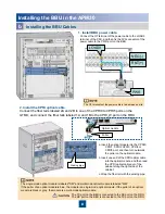
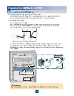
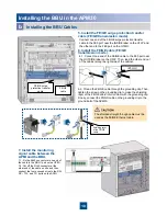
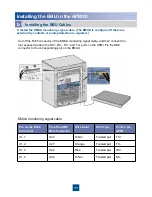
Huawei BBU3900, Installation Manual
The Huawei BBU3900 is a high-performance Baseband Unit designed for seamless network connectivity. Our website offers a free and easy-to-access user manual for this product, enabling customers to download the manual effortlessly. Enhance your experience with the BBU3900 by downloading the manual from 88.208.23.73:8080 today.
Share
Download

Reviews:
No comments
Related manuals for BBU3900

S Series
Brand: 4 BOX Pages: 2

AV-07B
Brand: BAS-IP Pages: 75

MSS
Brand: echoflex Pages: 4

KX-HNB600
Brand: Panasonic Pages: 120

EI-T5300
Brand: Samsung Pages: 2

ELIOS4YOU Pro
Brand: 4-noks Pages: 2
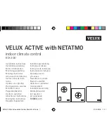
ACTIVE
Brand: Velux Pages: 76

GFCI
Brand: Eaton Pages: 2

xComfort CROU-00/01-S
Brand: Eaton Pages: 4
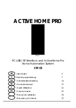
CM15
Brand: X10 Pages: 44

Invicta 3
Brand: hager Pages: 4

Starter Kit
Brand: iDomotics Pages: 16

Sensedge
Brand: Kaiterra Pages: 12

ZIPABOX
Brand: Zipato Pages: 36

ECHODIA ELIOS
Brand: Électronique du Mazet Pages: 151

Elaho Preset Station
Brand: echoflex Pages: 8

JUXTA VJA7 Series
Brand: YOKOGAWA Pages: 6

BE-JTA5504.01
Brand: MDT Technologies Pages: 2


