BBU
Alarm
Port
Pin on the
RJ45
Connecto
r at One
End
Wire
Color
Wire
Type
Pin on the
RJ45
Connecto
r at the
Other
End
Description
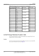
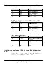
X1.3
White and
green
Twisted
pair
X2.3
Boolean value input 1+
X1.6
Green
X2.6
Boolean value input 1-
(GND)
X1.5
White and
blue
Twisted
pair
X2.5
Boolean value input 2+
X1.4
Blue
X2.4
Boolean value input 2-
(GND)
X1.7
White and
brown
Twisted
pair
X2.7
Boolean value input 3+
X1.8
Brown
X2.8
Boolean value input 3-
(GND)
4.17 GPS Clock Signal Cable
The GPS clock signal cable is an optional cable that transmits GPS clock signals from the GPS
antenna system to the BBU. The GPS clock signals serve as the clock reference of the BBU.
Exterior
The GPS clock signal cable has an SMA male connector at one end and an N-type female
connector at the other end, as shown in
Figure 4-23
GPS clock signal cable
(1) SMA male connector
(2) N-type female connector
4 BBU3900 Cables
BBU3900
Hardware Description
4-24
Huawei Proprietary and Confidential
Copyright © Huawei Technologies Co., Ltd.
Issue 11 (2010-11-10)
Summary of Contents for BBU3900
Page 1: ...BBU3900 V200 Hardware Description Issue 11 Date 2010 11 10 HUAWEI TECHNOLOGIES CO LTD ...
Page 2: ......
Page 4: ......
Page 14: ......
Page 56: ......

