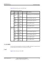
Table 3-75
Indicators for the TOD ports
Color
Status
Description
Green (on the left)
The green indicator is steady
on and the orange indicator is
steady off.
The TOD port is configured as
an input port.
Orange (on the right)
The orange indicator is steady
on and the green indicator is
steady off.
The TOD port is configured as
an output port.
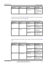
Ports
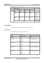
describes the ports on the USCU.
Table 3-76
Ports on the USCU
Silkscreen
Connector
Description
GPS
SMA connector
The GPS ports on the USCUb12, USCUb21,
USCUb14 and USCUb22 receive GPS signals.
The GPS port on the USCUb11 is reserved and
cannot receive GPS signals.
RGPS port
PCB welded
wiring terminal
The RGPS port on the USCUb11 receives RGPS
signals.
The RGPS ports on the USCUb12, USCUb21,
USCUb14 and USCUb22 are reserved and cannot
receive RGPS signals.
TOD0 port
RJ45 connector
This port receives or transmits 1PPS+TOD signals.
TOD1 port
RJ45 connector
This port receives or transmits 1PPS+TOD signals,
and receives TOD signals from the M1000.
BITS port
SMA connector
This port receives BITS clock signals, supports
adaptive input of 2.048 MHz and 10 MHz clock
reference source.
M-1PPS port
SMA connector
This port receives 1PPS signals from the M1000.
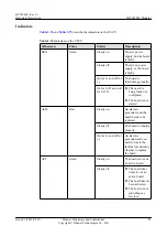
3.1.16 UBRI
The universal baseband radio interface board (UBRI) provides extended CPRI optical or
electrical ports to implement convergence, distribution, and multi-mode transmission on the
CPRI.
Panel
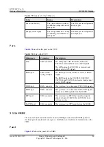
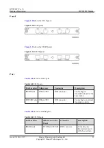
shows the panel of the UBRI.
BTS3900C (Ver.C)
Hardware Description
3 BTS3900C Modules
Issue 03 (2013-05-27)
Huawei Proprietary and Confidential
Copyright © Huawei Technologies Co., Ltd.
86


