l
Performs configuration management, device management, performance monitoring,
signaling message processing, and active/standby switchover.
l
Controls all boards in the system.
l
Provides the reference clock for the entire system.
l
Implements transmission and provides absolute time and 1 pulse per second (PPS) reference
clock source while being equipped with a single satellite card.
l
Provides four E1 ports and two FE/GE ports to implement basic transmission in compliance
with Asynchronous Transfer Mode (ATM), Internet Protocol (IP), and Point-to-Point
Protocol (PPP) during the initial configuration.
Ports
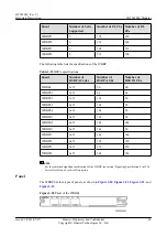
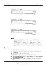
describes the ports on the UMPT.
Table 3-10
Ports on the UMPT
Silkscreen
Connector
Description
FE/GE1
SFP female
connector
A 100 Mbit/s or 1000 Mbit/s adaptive Ethernet
optical port is used for transmitting service data
and signaling messages.
FE/GE0
RJ45 connector
A 10 Mbit/s, 100 Mbit/s, or 1000 Mbit/s adaptive
Ethernet electrical port is used for transmitting
service data and signaling messages.
USB
(1)
USB connector
The USB port with the USB silkscreen is used for
the software upgrade of a base station using a USB
flash driver. This port also functions as a
commissioning Ethernet port
(2)
.
The USB port with the CLK silkscreen functions
as the TOD clock or test clock port.
E1/T1
DB26 female
connector
The port is used for four E1/T1 signal inputs and
outputs between the UMPT and universal E1/T1
lightning protection unit (UELP) or between base
station controllers.
GPS
SMA connector
The GPS port on the UMPTa1, UMPTb1, or
UMPTa2 is reserved.
The GPS port on the UMPTa6 is used for
transmitting radio frequency (RF) signals
received from the antenna to the satellite card.
CI
SFP female
connector
The port is used for BBU interconnection.
RST
-
The port is used to reset the board.
BTS3900C (Ver.C)
Hardware Description
3 BTS3900C Modules
Issue 03 (2013-05-27)
Huawei Proprietary and Confidential
Copyright © Huawei Technologies Co., Ltd.
31


