


DPU40D-N06A3, DBU20B-N12A3, and
DBU50B-N12A1 Distributed Power System
User Manual
5 Maintenance
Issue 04 (2020-02-29)
Copyright © Huawei Technologies Co., Ltd.
32
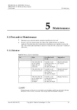
No.
Item
Possible Fault Cause
Suggestion
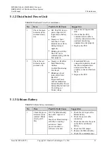
cable connection.
Blinking fast (4 Hz): The
communication is
interrupted.
1.
Check the communications
cable connection.
2.
Check whether the PSU is
normal. Replace the PSU if
it is abnormal.
2
Check the red
indicator status
(normal: off).
Steady on: Board
Hardware Fault/Heater
Fault/Electrochemical cell
fault/Duplicate address.
Replace the lithium battery.
Blinking at short intervals
(0.5 Hz): Discharge
Overcurrent
Protection/Charge
Overcurrent
Protection/Overtemperatur
e protection/Low
Temperature
Protection/Abnormal
shutdown/Charge
Overcurrent
Protection/Discharge
Overcurrent Protection.
Handle the alarm based on the
alarm type.
5.1.4 Cable
Table 5-4
Cable maintenance
No.
Item
Possible Fault
Cause
Suggestion
1
Check whether
signal cables and
power cables are
separately bound.
Cables are not
properly installed.
Install cables
properly, and bind
signal cables and
power cables
separately.
2
Check whether all
cables are bound
properly.
Cables are not
properly installed.
Bind cables
properly.
3
Check whether the
equipment ground
bar is securely
connected to the site
ground bar.
Cables are not
properly installed.
Connect the
equipment ground
bar to the site
ground bar.
4
Check whether
ground cables are
rusty.
Cables corrode after
being used for a
long time.
Replace rusty
cables.


