background image

EDGE U0-6 Simplified Maintenance Manual 

10 Troubleshooting 


Issue 1.0 (2013-01-12) 

Huawei Proprietary and Confidential           

Copyright © Huawei Technologies Co., Ltd. 

59 


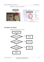
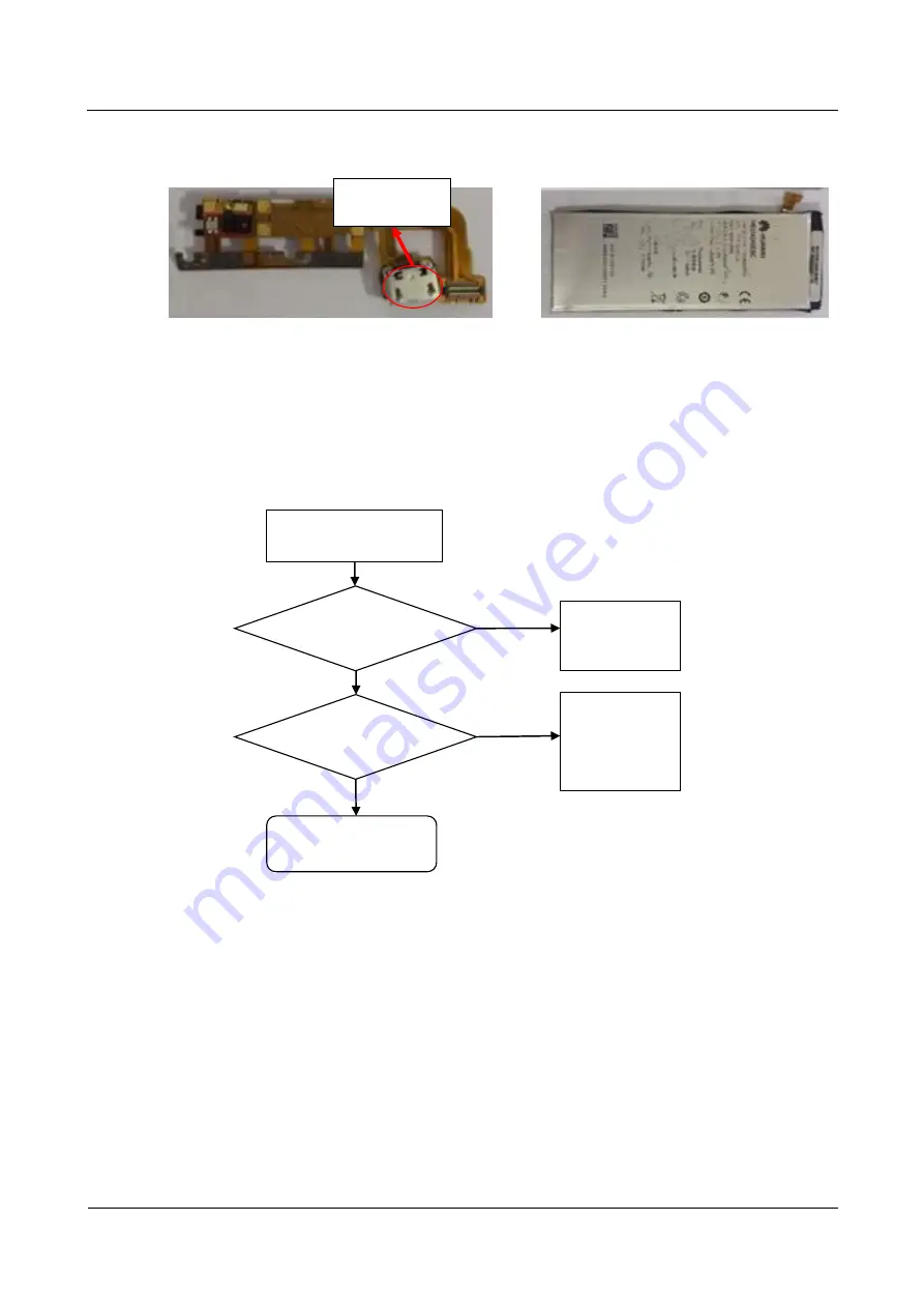
Figure 10-10


Critical parts for charging failures 


10.5 No Ringtone 

Figure 10-11


Troubleshooting ringtone failures 

No ringtone

Is the speaker 

properly 

functioning?

N

Replace the 

speaker

Y

Is the speaker signal 

circuit normal?

N

Check the 

connection of 

LB1202 and 

LB1203

Y

Re-solder or replace 

J2205 and J2206


USB port 

Summary of Contents for EDGE-U06

Page 1: ...EDGE U06 Simplified Maintenance Manual 2 0 Issue 2 0 Date 2013 10 12 HUAWEI TECHNOLOGIES CO LTD ...

Page 2: ...he customer All or part of the products services and features described in this document may not be within the purchase scope or the usage scope Unless otherwise specified in the contract all statements information and recommendations in this document are provided AS IS without warranties guarantees or representations of any kind either express or implied The information in this document is subjec...

Page 3: ...1 14 Approved by Service representative Date 2013 01 14 Change History Date Version Revision Reason Changed Chapter Description Author 2013 01 12 V1 0 Released the first version R D 2013 10 12 V2 0 Optimized the description of how to disassemble the phone Revised chapters 7 and 8 and added chapter 12 1 Highlighted the revised sections of chapters 7 and 8 in yellow 2 Added chapter 12 to provide gui...

Page 4: ... 7 4 2 How to Obtain Part Numbers 10 5 Software Upgrade 13 5 1 Upgrade Preparation 13 5 2 Checking the Software Version 14 5 3 How to Distinguish Between Software Versions 14 5 3 1 Software Types 14 5 3 2 Software Naming Convention 15 5 4 How to Obtain the Version Software 16 5 4 1 Method 1 16 5 4 2 Method 2 16 5 5 Using the microSD Card for Upgrade 17 5 5 1 Normal Upgrade 17 5 5 2 Forcible Upgrad...

Page 5: ...ormation 50 10 Troubleshooting 52 10 1 Power on Failure 52 10 2 Restarts and Screen Freezing 56 10 3 Overheat and Short Standby Time 57 10 4 Charging Failure 58 10 5 No Ringtone 59 10 6 Receiver Failure 60 10 7 Microphone Failure 61 10 8 Weak or No Reception 62 10 9 SIM Card Detection Failure 63 10 10 Camera Failure 63 10 11 Touchscreen Failure 64 11 Quality Inspection Procedure and Methods 65 11 ...

Page 6: ...Although every effort was made to ensure the accuracy of the document errors may still exist If you find any errors or have any suggestions please report them through Huawei service platform ComPartner 1 2 Brief Introduction This document introduces the product features mechanical parts assembly and disassembly procedures and common troubleshooting methods You will be able to clear common faults o...

Page 7: ...l 2 Product Overview Issue 1 0 2013 01 12 Huawei Proprietary and Confidential Copyright Huawei Technologies Co Ltd 2 2 Product Overview 2 1 Appearance Figure 2 1 shows the appearance of the HUAWEI EDGE U0 6 mobile phone U0 6 Figure 2 1 U0 6 ...

Page 8: ...tion Type Bar type Display Size 4 7 inches Type In Cell Color 16 M Resolution 1280 x 720 pixels Dimensions Claimed dimensions 132 6 mm x 65 5 mm x 6 18 mm 5 22 in x 2 58 in x 0 24 in Weight 120 g including the battery Technical standards GSM WCDMA HSPA HSDPA HSUPA 3GPP TS 34 114 Frequency bands WCDMA Band I 2100 MHz 1920 1980 MHz UL 2110 2170 MHz DL WCDMA Band II 1900 MHz 1850 1910 MHz UL 1930 199...

Page 9: ...E Multi slot classes Class 10 SIM card interface Standard 6 pin micro SIM card interface hot swapping not supported Expansion interfaces Standard micro USB port microSD card slot and 3 5 mm headset jack Expansion storage microSD card of up to 32 GB Processor Quad core 1 5 GHz CPU K3V2 Intel XMM6260 Phone storage ROM 8 GB RAM 2 GB Device control Power key volume keys and charging indicator GPS GPS ...

Page 10: ... transmission power WCDMA Band I 2100 MHz Band V 850 MHz Band VIII 900 MHz 23 dBm Power Class 3 Band II 1900 MHz Band IV 1700 MHz 22 5 dBm Power Class 3 GSM 850 MHz 900 MHz 32 5 dBm Power Class 4 GSM 1800 MHz 29 5 dBm Power Class 1 GSM 1900 MHz 29 dBm Power Class 1 Static sensitivity WCDMA Band I 2100 MHz Band II 1900 MHz Band IV 1700 MHz Band V 850 MHz Band VIII 900 MHz 110 dBm 3 84 MHz GSM 850 M...

Page 11: ...ceiver 30 Primary microphone 29 PCBA 28 Main antenna 6 Proximity sensor rubber 7 Secondary microphone rubber 27 Speaker 26 Primary microphone rubber 12 USB porot plastic support 13 USB port metal support 8 Receiver stiffening board 14 microSD card holder 15 SIM card holder 17 Motor support 19 BTB connector support 25 Main antenna support 24 Front cover decoration 23 Headset jack cover with the eje...

Page 12: ...arts Figure 4 1 is for your reference only It is subject to changes without notice Obtain the latest component information from the Huawei TCS If you have any questions contact the local technical support Table 4 1 Commonly used parts Part name CMOS FSI sensor 5 MP Part name CMOS BI sensor 8 MP Part name Battery Part name Speaker FPC Part name Headset jack FPC Part name Receiver FPC ...

Page 13: ...Confidential Copyright Huawei Technologies Co Ltd 8 Part name Proximity sensor rubber Part name Receiver Part name RF coaxial cable 50 5 mm Part name Motor support Part name USB port plastic support Part name USB port metal support Part name microSD card holder white Part name SIM card holder white ...

Page 14: ...e 1 0 2013 01 12 Huawei Proprietary and Confidential Copyright Huawei Technologies Co Ltd 9 Part name Terminal antenna Part name Rear camera lens Part name TP front LCD Receiver Speaker Antenna housing assembly used for repair Part name Battery cover assembly ...

Page 15: ... the correctness of a PN query the latest BOM information from https tcs huawei com before you apply for a part To check a PN use the authorized ASC account to visit the BOM system To query the BOM information and part pictures in the BOM system Step 1 Log in to the BOM system Figure 4 1 Login dialog box Step 2 Choose Basic Information BOM Tree Info Define the values for Product Line Product Type ...

Page 16: ... 12 Huawei Proprietary and Confidential Copyright Huawei Technologies Co Ltd 11 Figure 4 2 PN tree Step 3 Click the PN of the part to query The system displays the picture of the part Use the picture to confirm whether the part is what you want Figure 4 3 Part picture End ...

Page 17: ...ogies Co Ltd 12 To query the maintenance level for a part Step 4 Choose Basic Information Material Info enter the PN or description to query the maintenance level maintenance price and product on which the part is used Figure 4 4 Entering the part code Step 5 Click the PN The system displays the part picture Figure 4 5 Part picture End ...

Page 18: ...product line USB driver Upgrade tool WH62406270ML01_Ver1008_05010BXJ supports multiple upgrades simultaneously Upgrade file UPDATE APP Use the latest version for the upgrade Upgrade method Using the microSD card Normal upgrade Forcible upgrade Using the USB cable Normal upgrade Forcible upgrade Online upgrade When a Wi Fi network is available the phone downloads the upgrade package and automatical...

Page 19: ... powered on Forcible upgrades may be risky because information loss might happen and thus is not recommended About backing up important user data To back up contact information text messages and third party applications insert a microSD card and use the backup software on the phone All Backup for example to back up all the information to the microSD card To back up photos videos music and personal...

Page 20: ...ftware applies to the EDGE U00 The software PN is 05020CFV The software package includes the following folders Bootloaderimage contains the file that is used in factory software download USB COM ports match HDEDGEU00M004 the file is used in factory software download and earse operation 004 stands for the edition NO please download the newest edition from ComPartner Other files contains the config ...

Page 21: ...tep 2 On the displayed dialog box enter the IMEI of the phone select Physical Number and click Query Alternatively enter the PN of the version software select Other Code and click Query Step 3 Select the desired software from the displayed query results and click Download Figure 5 4 Entering the phone IMEI End 5 4 2 Method 2 Log in to http support huaweidevice com select the desired phone model cl...

Page 22: ...croSD Card for Upgrade 5 5 1 Normal Upgrade Step 1 Format the microSD card using FAT32 Step 2 Create a dload folder in the microSD card s root directory Figure 5 6 dload folder Step 3 Copy the upgrade file UPDATE APP to the dload folder Step 4 Insert the microSD card into the phone and power on the phone On the dialing screen enter 2846579 Choose ProjectMenu Upgrade SD card upgrade and touch Confi...

Page 23: ...are Upgrade Issue 1 0 2013 01 12 Huawei Proprietary and Confidential Copyright Huawei Technologies Co Ltd 18 Figure 5 7 Operations on the phone for a normal upgrade using the microSD card The screen shows the upgrade progress as shown in Figure 5 8 ...

Page 24: ...nd 5 5 2 Forcible Upgrade If the phone cannot be powered on forcibly upgrade the phone Press and hold the volume up and volume down keys and press the power key at the same time The phone then enters the microSD card forcible upgrade mode The upgrade process displayed on the screen is the same as the normal upgrade If the phone fails to be upgraded forcibly it cannot be detected by the computer To...

Page 25: ...upgrade Figure 5 10 Files in the Hisi Platform Usb Driver package Step 2 After the installation is complete power on the phone Step 3 Connect the phone to the computer using a USB cable Access Device Manager and check whether the port information is correct If the phone port is not detected switch the phone to normal mode To switch the phone to manufacture mode on the phone dialing screen enter 28...

Page 26: ...ep 3 Choose the phone model In the left navigation tree select Upgrade Tool On the right panel double click the upgrade tool In the displayed dialog box enter the password Huawei and click OK Figure 5 12 Upgrade tool Step 4 Select files Select the upgrade file with the file name extension APP for Firmware Select the configuration file of the upgrade tool for Please Choose The configuration File Th...

Page 27: ...ht Huawei Technologies Co Ltd 22 Step 5 Click Scan Download to start the upgrade as shown in Figure 5 14 Figure 5 14 Clicking Scan Download Figure 5 15 Upgrade process After the upgrade is complete the upgrade tool displays Download Success as shown in Figure 5 16 Step 6 Wait for two or more seconds and remove the USB cable ...

Page 28: ...nnect the phone to the computer using a USB cable The phone automatically enters forcible upgrade mode Then use the upgrade tool to upgrade the phone 5 7 Troubleshooting Upgrade Failures Table 5 2 Upgrade failures and solutions Failure Solution Computer Failed to detect the phone s presence 3 Check whether there is any other driver conflicting the USB driver 4 Check whether the USB driver has been...

Page 29: ...tary and Confidential Copyright Huawei Technologies Co Ltd 24 Failure Solution Failed to upgrade a phone using a microSD card 1 Check whether the upgrade file is correct 2 Check whether the upgrade method is correct 3 Check whether the microSD card functions properly 4 Perform the upgrade again ...

Page 30: ...roprietary and Confidential Copyright Huawei Technologies Co Ltd 25 6 Maintenance Tools Name heat gun Usage heats components Name heat gun Usage heats components Name soldering iron Usage solders components Name DC power supply Usage supplies power Name soldering fixture Usage secures PCBAs ...

Page 31: ...parameters during maintenance Name toolkit Usage assembles and disassembles terminals Name electric screwdriver Usage fastens and removes screws Name RF switch wrench Usage removes RF switches Name EDGE battery cover tear down camp Item code 02430834 Usage Battery cover tear down Mark This camp is used in big repair center Name EDGE battery cover assemble camp Item code 02430833 Usage Battery cove...

Page 32: ...e Manual 6 Maintenance Tools Issue 1 0 2013 01 12 Huawei Proprietary and Confidential Copyright Huawei Technologies Co Ltd 27 Name Knife Usage Tear down mobile phone Name Cupule Usage Tear down battery cover Mark Used for ASC repair ...

Page 33: ...ietary and Confidential Copyright Huawei Technologies Co Ltd 28 7 Disassembly Procedure 1 Prepare the spudger vacuum sucking nozzle T5 screwdriver and tweezers 2 Wear an ESD wrist strap 3 Use the eject tool to expel the SIM card and microSD card holders from the phone 4 Remove the two card holders ...

Page 34: ...aker anti dust mesh 6 Lift the decoration and remove it by turning it Do not scratch the main antenna 7 Remove the adhesive residuals The removed decoration will be scrapped Therefore lift the decoration as high as possible to avoid damaging the main antenna when you attempt to remove the decoration 8 Close up picture of the phone after the decoration is removed 9 Wear a pair of anti skid ESD glov...

Page 35: ...p of the phone apply force in the Z direction to remove the battery 12 After the battery cover is removed scrap the camera lens and attach rear camera adhesive to the GPS antenna rack 13 Remove the tamper resistant label using the tweezers 14 Remove the screws on the motor metal sheet and LCD metal sheet using the electrical screwdriver 15 Remove the two metal sheets with caution Do not damage sur...

Page 36: ...ters Do not use metal or sharp objects to remove the battery 19 Use the card to cut the adhesive along the battery the sdhesive must be cut completely and pry the battery from one side Do not pry the battery from its top or bottom 20 When removing the battery use the straight edge of the battery removal card instead of its round corners Do not remove the battery when the battery power is full It i...

Page 37: ...cratching it If bulging of the battery smoke fire or other exceptions occur when you remove the battery immediately place the battery in the safety isolation area stay away from the battery and notify the security personnel 22 Remove the four screws that fix the GPS antenna rack in sequence 23 Pry the first buckle of the GPS antenna support The arrow in the above figure shows the prying force dire...

Page 38: ...lip on the right of the GPS antenna rack Apply force in the Z direction 27 Use tweezers to gently pry the fifth clip on the right of the GPS antenna rack Apply force in the Z direction 28 Use tweezers to gently pry the fourth clip on the right of the GPS antenna rack Apply force toward the outer side of the front cover 29 Slide the antenna left and right to release it from the last buckle on the Y...

Page 39: ...is not reused Use a marker to mark an X on both sides of the battery or make other signs that indicate the battery is to be scrapped 32 Release the receiver FPC and use a coaxial cable screwdriver to release the connectors for the coaxial cable Apply force in the vertical direction to avoid damaging the connectors for the coaxial cable 33 Release the LCD BTB connector from the PCBA 34 Pry the moto...

Page 40: ...o not damage any component when you pry the PCBA 38 After the PCBA is lifted remove it upward Do not drag the LCD BTB connector 39 The PCBA is removed 40 Remove the secondary microphone rubber using the tweezers then Remove the two screws that fix the receiver FPC 41 Pry the steel stiffening board using the box cutter 42 Slightly pry the FPC up using the box cutter ...

Page 41: ...d 36 43 Release the ground connector of the FPC Do not scratch the FPC 44 The FPC is removed 45 Insert the tweezers into the screw hole push downward to remove the lower metal support 46 Pry the plastic support up and remove it Remove the USB component gently 47 Release the speaker buckles 48 Gently press the headset jack FPC Lift the main antenna support ...

Page 42: ...hesive using the box cutter Do not damage the microphone FPC or surrounding components 52 Insert the tweezers into the screw hole and push to the upper right direction 53 Slide the receiver rightward using the tweezers to remove it 55 Never disassemble the phone the way shown in the above figure Use plastic tweezers to pry the shielding covers on both sides of the battery which exposes the shieldi...

Page 43: ...ght when fastening the BTB connectors Criteria The BTB connectors are properly fastened to the PCBA 3 Take a front cover assembly and remove the protective film from the front camera and front camera lens Clean the camera and lens using the ion gun 4 Bend the headset jack FPC rightward Way of bending Press the corner R of the FPC using a finger of your right hand Bend the BTB connector area using ...

Page 44: ...the PCBA 9 Bend the headset jack FPC to the bottom of the phone 10 Turn the motor anticlockwise for three circles Remove the motor release paper and place the assembly into the fixture Use the cable sorting tool to sort the motor cables Criteria The motor is smoothly attached The motor cable does not exceed the motor height The motor cable is pressed by the motor The connector of the cable is Inse...

Page 45: ...The BTB connector is properly fastened to the PCBA 12 Install the motor support 13 Tighten the screws that are used to fix the motor support using the screwdriver and correct screw tightening jig Sequence of tightening the screws See the above figure Torque 0 7 0 8 kgf cm Speed low Criteria No screws or threads are stripped out 14 Install the TP and LCD BTB connector protective support The motor s...

Page 46: ...ig to attach the receiver FPC and proximity sensor FPC to the stiffening board 18 Take out the receiver FPC and install a proximity sensor rubber to the proximity sensor Note The rubber s protruding part must be stuck in the cut of the stiffening board 19 Remove the release paper from the receiver FPC 20 Install the USB connector to the front cover Criteria The USB connector is properly installed ...

Page 47: ...he screwdriver with the torque of 0 6 0 7 kgf cm 24 Remove the release paper from the ground spot of the receiver FPC fasten the receiver BTB connector to the PCBA and attach the FPC to the USB port metal support Criteria The BTB connector is properly fastened to the PCBA 25 Remove the release paper from the secondary microphone on the receiver FPC Install the secondary microphone rubber Criteria ...

Page 48: ...ble in its slot and connect the cable to the receiver FPC 27 Bend the battery FPC in the way shown in the above figure 28 Check that there are no foreign materials in the battery compartment or on the battery Fasten the battery BTB connector to the PCBA and install the battery into the battery compartment Criteria The BTB connector is properly fastened to the PCBA 29 move the battery back about 20...

Page 49: ...nd to the screw in the upper left corner of the battery and a waterproof label next to the camera then press the label using a cotton swab 34 Check that the LCD FPC s ground pad is properly attached remove the release paper from the battery compartment and attach the battery by aligning it with the side of the compartment next to the PCBA Check that the coaxial cable is above the battery FPC If no...

Page 50: ...39 Remove the board SN label camera hole protective film and release paper on the rear camera lens 40 get 1pcs Conductive Foil which item code is 51634744 then attach the conductive foil to the GPS antenna support by aligning it with the upper left corner of the front camera Criteria The conductive foil can t cover on the frame of A cover 41 Take a battery cover and remove the release paper from t...

Page 51: ...place To avoid distorting the clips a Before you push the battery cover make sure it is smoothly installed b When you are pushing the battery cover try to apply force evenly 44 Check whether the gaps between the battery cover and front cover comply with the standard 45 Remove the release paper from the adhesive on the lower part of the front cover 46 Place the decoration on the phone as shown in t...

Page 52: ... 2013 01 12 Huawei Proprietary and Confidential Copyright Huawei Technologies Co Ltd 47 47 Install the rear camera lens to the phone using the vacuum sucking pen 48 After you install the rear camera lens press the jig to press fit the lens with your hands for 5 6 seconds ...

Page 53: ... party applications Solution Upgrade the phone to the latest version software 9 2 I forgot the screen lock password What can I do Solution Forcibly unlock the phone which will erase all user information After the phone is powered off press and hold the power volume up volume down keys When the startup screen is displayed wait for 3s and then release the power key After the recovery screen shown in...

Page 54: ... Simplified Maintenance Manual 9 FAQs Issue 1 0 2013 01 12 Huawei Proprietary and Confidential Copyright Huawei Technologies Co Ltd 49 Figure 9 1 Recovery screen Figure 9 2 Scrolling to Yes delete all user data ...

Page 55: ...Other issues Solution Restore the phone to its factory settings To restore the phone to its factory settings choose Settings Backup reset Factory data reset Reset phone Figure 9 3 Operations on the phone for restoring it to its factory settings 9 4 How do I check my phone s Wi Fi Bluetooth SN information To check the Wi Fi and Bluetooth addresses Enable Bluetooth and Wi Fi on your phone Choose Set...

Page 56: ...E U0 6 Simplified Maintenance Manual 9 FAQs Issue 1 0 2013 01 12 Huawei Proprietary and Confidential Copyright Huawei Technologies Co Ltd 51 Figure 9 4 Wi Fi and Bluetooth addresses Figure 9 5 IMEI and SN ...

Page 57: ...s and hold the power key the phone fails to start and display the Home screen Solution Check whether the problem is caused by a battery fault 1 Check whether the battery is deformed and properly fits in the battery compartment 2 Check whether the contacts on the battery are smudged or rusted If yes clean the contacts 3 Use the multimeter to test the ground impedance of the battery s BSI 4 The norm...

Page 58: ...ry and in the battery compartment deformed or smudged Power on failure N Y Clean the contacts Y Confirm the fault cause N Replace the battery Figure 10 2 Troubleshooting battery failures Is the battery BSI s ground impedance is 10 kohms Is the battery voltage larger than or equal to 3 7 V after the battery is charged for 30 minutes Battery failure N Y Confirm the conclusion that the battery is pro...

Page 59: ...wer key functions properly Change the PCBA if the failure is not caused by the power key Weak current 25 80 mA Forcibly upgrade the phone software using a microSD card or USB cable If the upgrade fails replace the PCBA Excessive current or high current If the current is above 800 mA replace the PCBA Troubleshooting Process Troubleshooting process for no current power on failures Figure 10 4 Troubl...

Page 60: ...Huawei Proprietary and Confidential Copyright Huawei Technologies Co Ltd 55 Figure 10 5 Battery interface circuit diagram Figure 10 6 Critical parts on the PCBA for power on failures Troubleshooting process for weak current power on failures Battery connector J1301 Power key S2201 ...

Page 61: ... the PCBA Y N Troubleshooting process for excessive current power on failures Replace the PCBA directly 10 2 Restarts and Screen Freezing Symptom After you press and hold the power key the phone repeatedly restarts and cannot display the Home screen After you press and hold the power key the phone freezes at the Huawei logo screen and cannot display the Home screen Solution Check the power on curr...

Page 62: ... is forcibly upgraded End Replace the PCBA Y N Y N 10 3 Overheat and Short Standby Time Symptom The phone gets overheated after startup and the standby time is short Solution Test the VBAT s ground impedance If the impedance is less than 5 kohms the problem is probably caused by the PCBA Test the power off current If the current exceeds 1 mA the problem is caused by the PCBA Test the power on and ...

Page 63: ... USB cable If yes replace the PCBA With charging icon Test whether the BSI s ground impedance is 10 kohms and whether the voltage between the battery s positive and negative terminals is 0 V If the voltage is 0 V while the impedance is much larger or smaller than 10 kohms the battery is faulty Replace the battery and check whether the phone can be properly charged If the problem persists replace t...

Page 64: ...echnologies Co Ltd 59 Figure 10 10 Critical parts for charging failures 10 5 No Ringtone Figure 10 11 Troubleshooting ringtone failures No ringtone Is the speaker properly functioning N Replace the speaker Y Is the speaker signal circuit normal N Check the connection of LB1202 and LB1203 Y Re solder or replace J2205 and J2206 USB port ...

Page 65: ...cal parts for ringtone failures 10 6 Receiver Failure Figure 10 13 Troubleshooting receiver failures Receiver failure Is the receiver properly functioning N Replace the receiver Y Is the receiver FPC properly functioning N Replace the receiver FPC Y Are the related signal circuits properly functioning N Exclude the circuit faults Y Replace the PCBA J2206 J2205 LB1202 LB1203 ...

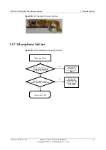
Page 66: ...part for receiver failures 10 7 Microphone Failure Figure 10 15 Troubleshooting microphone failures Microphone failure Are the microphone and microphone sub board properly functioning N Replace the microphone or microphone sub board Y Are the related signal circuits properly functioning N Exclude the microphone sub board FPC and related signal circuit faults Y Replace the PCBA ...

Page 67: ...ential Copyright Huawei Technologies Co Ltd 62 10 8 Weak or No Reception Figure 10 16 Troubleshooting reception failures No reception Weak reception Is the SIM card malfunctioning Replace the SIM card with a standard one Is the main antenna malfunctioning Replace the main antenna Replace the PCBA Yes Yes No No ...

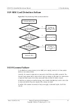
Page 68: ...tioning N Re solder or replace damaged parts Y Replace the PCBA 10 10 Camera Failure To troubleshoot a camera failure use the MMI test to identify whether it is a front camera failure or rear camera failure Currently the camera components are connected to the PCBA using BTB connectors The front and rear cameras share a main cable If only one camera is abnormal it is considered as a single unit fau...

Page 69: ... Touchscreen Failure When a touchscreen failure occurs the LCD display is normal but you cannot unlock the screen The TP assembly has a great independence and multiplex power supply and communication interfaces with other circuits Therefore you can replace the front cover to identify whether the failure is a touchscreen failure or a PCBA related circuit failure ...

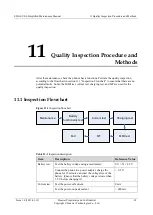
Page 70: ...the MMI test current test charging test and MT are used for the quality inspection 11 1 Inspection Flowchart Figure 11 1 Inspection flowchart Maintenance MMI test Battery functionality test Current test MT Charging test End Table 11 1 Inspection description Item Description Reference Value Battery test Test the battery voltage using a multimeter 0 V X 4 5 V Connect the phone to a power adapter cha...

Page 71: ... the power remaining of the battery is lower than 50 before charging it 3 MMI test Test the functions of the peripheral parts such as the audio and display components All pass MT Test the phone s reception on 2G and 3G networks All pass 11 2 Inspection Tools Table 11 2 Inspection tools Tool Function Picture Multimeter Used for the battery test Tests the battery voltage DC power supply Used for the...

Page 72: ... Headset Used for the MMI test Tests the headset and FM functions of the phone Charger Used for the charging test and battery test Charges the phone USB cable Used for the charging test and battery test Charges the phone WILLTEK CMU200 Used for the MT Tests the phone s reception metric Antenna coupler Used for the MT Tests the phone s reception metric Couples phone signals Shielding box Used for t...

Page 73: ...pection Figure 11 2 Test point 11 3 2 Current Test Testing the Power off Current Remove the battery from the phone connect the phone to the DC power supply power off the phone and check the current If the reading on the power supply is not 0 mA current leakage occurs Testing the Power on Peak Current Remove the battery from the phone connect the phone to the DC power supply power on the phone and ...

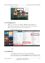
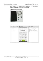
Page 74: ...s Battery level Step 2 Charge the phone using the power adapter for 10 minutes and check the battery level Step 3 If the battery level does not increase a charging failure occurs Figure 11 4 Operations on the phone End 11 3 4 MMI Test After maintenance check the functions of the phone through the MMI test To enter MMI test mode insert a microSD card and a SIM card into the phone power on the phone...

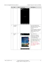
Page 75: ...t Touch the menu key on the touchscreen to skip the current test item and proceed to the next Touch the return key to return to the previous test item Figure 11 5 Preparation for the MMI test Table 11 3 MMI test instructions No Item Step Description Instructions 1 Enter MMI test mode 1 On the dialing screen enter 2846579 to enter MMI test mode Press the volume down key to start the test ...

Page 76: ...ically proceeds to the next test item if the microSD card is detected If the microSD card cannot be detected the failure message will be displayed on the screen 3 Keypad test 3 Press all the keys When a key is pressed or touched the color of the corresponding area on the screen should change After all keys are tested press the volume down key to proceed to the next test item Mark only test power k...

Page 77: ...he phone starts this test item it displays the white screen Press the volume down key to display the black screen Press the volume down key to display the red screen Press the volume down key to display the green screen Press the volume down key to display the blue screen 5 LCD backlight test 5 If the LCD backlight repeatedly turns on and off the LCD backlight functions properly Press the volume d...

Page 78: ...tion Instructions 6 Rear camera test 6 After the phone displays the preview screen press the volume up key to take a picture If the flashlight blinks once this test item passes Press the volume down key to proceed to the next test item 7 Front camera test 7 After the phone displays the preview screen press the volume up key to take a picture Press the volume down key to proceed to the next test it...

Page 79: ...ssue 1 0 2013 01 12 Huawei Proprietary and Confidential Copyright Huawei Technologies Co Ltd 74 No Item Step Description Instructions Flashlight test 8 Touch the test bar the bar turns from red to green and the flashlight is on Press the volume down key to proceed to the next test item ...

Page 80: ...ntial Copyright Huawei Technologies Co Ltd 75 No Item Step Description Instructions 8 Touchscre en test 8 Touch the points on the screen from the top bottom to form vertical lines If the touchscreen functions properly the vertical lines you touched will change to color stripes Press the volume down key to proceed to the next test item ...

Page 81: ...r test 9 Place the shielding board above the touchscreen and keep it away from the photic hole for about 4 mm If a phone icon is displayed nearby the portrait the test item passes Press the volume down key to proceed to the next test item 10 Light sensor test 10 Check whether the environmental light data is detected Use your hand to block the light hole the value will decrease to approximately 10 ...

Page 82: ...tial Copyright Huawei Technologies Co Ltd 77 No Item Step Description Instructions 11 Motor test 11 The motor vibrates intermittently Press the volume down key to proceed to the next test item 12 Speaker test 12 If the speaker delivers soft and clear sound this test item passes Press the volume down key to proceed to the next test item ...

Page 83: ...Press the volume down key to proceed to the next test item 13 Primary microphon e loopback test 13 Touch Record Speak into the primary microphone and then touch Play If the microphone functions properly you can hear the voice recording from the receiver Use the similar method to test the secondary microphone and then the dual microphone Insert the headset into the phone and use the similar method ...

Page 84: ...ctions 14 FM test 14 After a headset is inserted the phone searches for and plays the program of an FM channel If you hear the program from the headset the test item passes Press the volume down key to proceed to the next test item 15 Headset wire control test 15 Insert the headset The in icon turns green Remove the headset and the out icon turns green Press the volume down key to proceed to the n...

Page 85: ...ei Technologies Co Ltd 80 No Item Step Description Instructions 16 Bluetooth test 16 The phone automatically tests the Bluetooth function During the test the phone searches for Bluetooth devices and displays the devices that have been found Press the volume down key to proceed to the next test item This test requires another device with Bluetooth enabled ...

Page 86: ...test item passes Press the volume down key to proceed to the next test item 19 Wi Fi test 19 If the phone displays information of a Wi Fi network that has been found this test item passes Another Wi Fi device whose Wi Fi function is enabled is required for the test SIM card test If the inserted SIM card functions properly this test item automatically passes Otherwise the failure message is display...

Page 87: ...into the shielding box and run the test software Before the test select the 2G and 3G bands If the test fails the RF metric of the phone is nonconforming and the RF components may be faulty Figure 11 6 MT scene How to understand the MT script Test Equipment The test equipment is AERROFLEX4400 of version 15 21 001 RF connection indicates the RF connection information The antenna coupler is Willtek ...

Page 88: ...s the transmit power of the phone If the result is FAIL the antenna or PA module may be damaged RX Level indicates the voltage level of the signals received by the phone If the result is FAIL the antenna or RF intermediate frequency IC may be damaged RBER short for residual bit error rate indicates the ratio of the received wrong bits to the sent bits It is an important receive quality metric in d...

Page 89: ...in Figure 4 a Use tweezers to gently pry the fifth clip on the left of the GPS antenna rack Apply force in the Z direction b Use tweezers to gently pry the fourth clip on the right of the GPS antenna rack Apply force gently downward and then pry the clip upward Figure 1 Figure 2 c Use tweezers to gently pry the third clip on the left of the GPS antenna rack Apply force from the inside of the front...

Page 90: ...gure 3 Figure 4 Figure 5 shows the bent GPS antenna rack Figure 5 2 Release the receiver FPC battery BTB connector and LCB BTB connector a Release the receiver FPC and battery BTB connector Then use the coaxial cable driver to release the coaxial cable connector Apply force vertically to avoid damaging the coaxial cable connectors b Release the LCD BTB connector Figure 1 Figure 2 The fifth clip ...

Page 91: ...two cameras a Gently pry the motor up using tweezers b Gently remove the two cameras from the front cover Note Do not damage surrounding components Figure 1 Figure 2 4 Pry the main antenna spring and PCBA a Use tweezers to pry the clip for the main antenna spring Then slowly lift the PCBA and do not damage the surrounding components Figure 1 Figure 2 b After the PCBA is lifted pull it out upward D...

Page 92: ...nologies Co Ltd 87 Figure 3 Figure 4 c Remove the front and rear cameras Figure 5 5 Restore the bent GPS antenna rack Applicable to scenarios of saving and returning materials a Restore the bent GPS antenna rack to its original position along the turning line and fasten the clips 3 4 5 and 6 b Attach protective film to the screen from the top of the phone and wrap the phone ...

Page 93: ... 0 2013 01 12 Huawei Proprietary and Confidential Copyright Huawei Technologies Co Ltd 88 Figure 1 Figure 2 Figures 3 and 4 show the phone with the protective film attached Figure 3 Figure 4 c Place the phone into the red ESD bag 12 2 Assembly Procedure 1 Install the front and rear cameras The fifth clip ...

Page 94: ... a front cover assembly and remove the protective film from the front camera and front camera lens Then clean the camera and lens using the ion gun b Straighten up the battery connector coaxial cable and headset jack FPC with your hands to avoid crushing them when you install the PCBA Figure 1 Figure 2 c When you install the PCBA make sure the power and volume keys are properly fastened into the c...

Page 95: ...od contact with the main antenna spring 3 Press fit the receiver FPC battery BTB connector and LCD BTB connector with your hands These three keys must be properly installed on the PCBA The positioning rod on the front cover must be properly connected to the positioning hole on the PCBA This clip on the PCBA must be connected to the positioning slot on the front cover This spring pin must be higher...

Page 96: ...e must not be higher than the motor surface The motor cable must not be pressed by the motor The connector of the cable must be positioned in the correct slot Figure 1 Figure 2 4 Fasten the GPS antenna rack a Fasten clips 3 4 5 and 6 Apply force from the left Success criteria Clips 3 and 4 must be properly fastened without being distorted Make sure the turning line is even If either of the precedi...

Page 97: ...0 8 kgf cm You can also manually fasten the screws Success criteria No screws or threads are stripped out b Install the protective rack for the TP LCD BTB connector and fasten the two screws at a low speed with the torque of 0 8 kgf cm You can also manually fasten the screws Success criteria No screws or threads are stripped out Figure 1 Figure 2 Figures 3 shows the phone with the protective racks...

Reviews: