background image

ETP4830-A1 Embedded Power 
User Manual 

1 Safety Precautions 


Issue 10 (2017-08-08) 

Huawei Proprietary and Confidential                                     

Copyright © Huawei Technologies Co., Ltd. 


Before drilling holes into a cabinet, wear goggles and protective gloves. Remove cables 
from inside the cabinet. 


After drilling, clean up any metal shavings that have accumulated inside or outside the 
cabinet. 

Moving Heavy Objects 


Only trained personnel are allowed to move heavy objects. 


Wear protective gloves and shoes before moving heavy objects. 


Be cautious to prevent injury when moving heavy objects. 


At least two people are required to move heavy objects. 


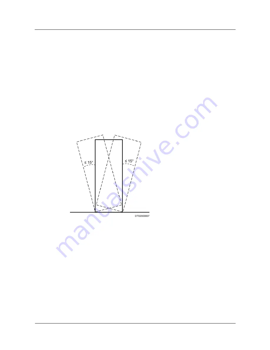
When you transport cabinets, ensure that there is no excessive tilt and no sudden jolt. 
The maximum allowed tilt angle when loading and unloading a cabinet is 15 degrees. 
Secure the cabinet to a pallet truck before you transport it. 


When you move a cabinet, ensure that it does not bump into other objects or fall down. 

Figure 1-2


Transportation gradient 


Summary of Contents for ETP4830-A1

Page 1: ...ETP4830 A1 Embedded Power User Manual Issue 10 Date 2017 08 08 HUAWEI TECHNOLOGIES CO LTD ...

Page 2: ... Huawei and the customer All or part of the products services and features described in this document may not be within the purchase scope or the usage scope Unless otherwise specified in the contract all statements information and recommendations in this document are provided AS IS without warranties guarantees or representations of any kind either express or implied The information in this docum...

Page 3: ...mbols that may be found in this document are defined as follows Symbol Description Indicates an imminently hazardous situation which if not avoided will result in death or serious injury Indicates a potentially hazardous situation which if not avoided could result in death or serious injury Indicates a potentially hazardous situation which if not avoided may result in minor or moderate injury Indi...

Page 4: ...e Issue 08 2014 10 30 Chapter 6 Commissioning Added section 6 5 Setting Battery Parameters Issue 07 2014 07 18 Chapter 6 Commissioning Modified 6 5 Setting Battery Parameters Added section 6 6 Optional Setting DC Parameters Issue 06 2014 02 20 Chapter 4 Installation Added section 4 3 2 Optional Installing Dry Contact Signal Cables Chapter 6 Commissioning Added section 6 4 Setting System Type Issue...

Page 5: ...0 A1 Embedded Power User Manual About This Document Issue 10 2017 08 08 Huawei Proprietary and Confidential Copyright Huawei Technologies Co Ltd iv Issue 01 2012 05 11 This issue is the first official release ...

Page 6: ...er 9 3 3 SMU 11 3 3 1 SMU01A 11 3 3 2 SMU01B 15 3 3 3 SMU01C 18 4 Installation 22 4 1 Installing a Subrack 22 4 2 Installing Components 23 4 2 1 Installing an SMU 23 4 2 2 Installing a Rectifier 23 4 3 Installing Cables 24 4 3 1 Connecting the Ground Cable 24 4 3 2 Optional Installing Dry Contact Signal Cables 24 4 3 3 Connecting the Communications Cable 25 4 3 4 Connecting the DC Load Cable 27 4 ...

Page 7: ... SMU01B and SMU01C 33 6 6 Optional Setting DC Parameters 34 6 7 Optional Setting Hibernation Parameters 34 6 7 1 SMU01A 34 6 7 2 SMU01B and SMU01C 35 6 8 Optional Setting Alarm Parameters 35 6 8 1 SMU01A 35 6 8 2 SMU01B and SMU01C 36 6 9 Optional Setting Communications Parameters 36 6 9 1 SMU01A 36 6 10 Connecting the Battery Supply 41 7 Maintenance 43 7 1 Routine Maintenance 43 7 2 Rectifying Com...

Page 8: ... Alarm 49 7 2 17 Rect Fault 49 7 2 18 Rect Protection 50 7 2 19 Single Rect Fault 50 7 2 20 Multi Rect Fault 50 7 2 21 Rect Comm Fault 51 7 3 Identifying Faults 51 7 3 1 Identifying Rectifier Faults 51 7 3 2 Identifying SMU Faults 52 7 4 Replacing Components 53 7 4 1 Replacing a Rectifier 53 7 4 2 Replacing an SMU 54 A Technical Specifications 56 B Acronyms and Abbreviations 60 ...

Page 9: ...t switch of the cabinet Comply with local laws and regulations The safety instructions in this document are only supplemental to local laws and regulations Do not operate the product or handle cables during thunderstorms Do not expose the equipment to flammable or explosive gas or smoke Keep batteries away from strong infrared radiation organic solvents and corrosive gas Do not use water to clean ...

Page 10: ...efore they are laid out Perform routine maintenance as described in this manual replace faulty components at the earliest After maintenance is completed lock cabinet doors and seal cable holes to prevent rodents from entering the cabinet 1 2 Electrical Safety Grounding When installing a device install the ground cable first When uninstalling a device remove the ground cable last Before operating a...

Page 11: ...strator 1 3 Battery Safety Before installing operating or maintaining the batteries read the battery manufacturer s safety instructions Observe the safety precautions provided in this section which are supplemental to the safety instructions provided by the battery manufacturer Basic Requirements Avoid skin contact with battery electrolyte Before handling batteries wear goggles rubber gloves and p...

Page 12: ... 60 C battery electrolyte may overflow If the electrolyte overflows wear goggles rubber gloves and protective clothing and absorb the leaking electrolyte using sodium bicarbonate NaHCO3 or sodium carbonate Na2CO3 Do not transport or move batteries if there is an electrolyte leakage Battery Overdischarge After connecting the batteries remove the battery fuse or turn the battery circuit breaker OFF ...

Page 13: ...objects ensure that hoisting tools are firmly fixed onto a load bearing object or wall Ensure that the angle formed by each hoisting cable is less than 90 degrees If metal hoisting cables are used place protective pads between the cables and the cabinet to prevent scratches to the cabinet surface Figure 1 1 Hoisting heavy objects Drilling Holes Do not drill holes into a cabinet without permission ...

Page 14: ...s Only trained personnel are allowed to move heavy objects Wear protective gloves and shoes before moving heavy objects Be cautious to prevent injury when moving heavy objects At least two people are required to move heavy objects When you transport cabinets ensure that there is no excessive tilt and no sudden jolt The maximum allowed tilt angle when loading and unloading a cabinet is 15 degrees S...

Page 15: ...MU01A communicates with Huawei Network Ecosystem NetEco and third party element management systems EMSs over various security protocols such as the Simple Network Management Protocol SNMP and Hypertext Transfer Protocol Secure HTTPS featuring flexible networking It provides WebUI and implements remote unattended management The SMU01B connects to the U2000 over Huawei master slave protocols Display...

Page 16: ...tion Item Configuration PDU AC input 230 V AC single phase three wire L N compatible with 230 V AC dual live wire L L DC power distribution Battery fuse One 20 A Load fuse Two 20 A SMU The following SMUs are supported One SMU01A One SMU01B One SMU01C Rectifier The following rectifiers are supported One to two R4815G1s One to two R4815N1s NOTE The R4815G1 and R4815N1 can be installed together ...

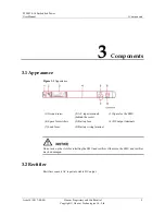
Page 17: ...ance Figure 3 1 Appearance 1 Ground screw 2 AC input terminals behind the cover 3 Space for the SMU 4 Space for rectifiers 5 Battery fuse 6 DC output terminals 7 Load fuses 8 Battery wiring terminal Do not mix up the slots for installing the SMU and rectifier Otherwise the SMU and rectifier may be damaged 3 2 Rectifier Rectifiers convert AC input into stable DC output ...

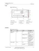
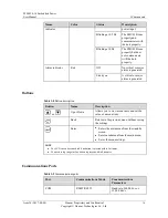
Page 18: ...0 5 Hz The rectifier is being queried Blinking at 4 Hz The rectifier is loading an application program Alarm indicator Yellow Off No alarm has been generated Steady on The rectifier has generated an alarm for power limiting due to ambient overtemperature The rectifier has generated an alarm for shutdown due to ambient overtemperature or undertemperature The rectifier is protecting itself against A...

Page 19: ... 10 2017 08 08 Huawei Proprietary and Confidential Copyright Huawei Technologies Co Ltd 11 Indicator Color Status Description output overvoltage The rectifier has no output due to an internal fault 3 3 SMU 3 3 1 SMU01A Appearance Figure 3 3 SMU01A appearance ...

Page 20: ...OM port 8 Locking latch 9 Buttons 10 LCD Indicators Table 3 2 Indicator description Name Color Status Description Running status indicator Green Off The SMU01A is faulty or has no DC input Blinking at 0 5 Hz The SMU01A runs properly and communicates with the host properly Blinking at 4 Hz The SMU01A runs properly but does not communicate with the host properly Alarm indicator Red Off No critical o...

Page 21: ...the main menu from the standby screen Enter a submenu from the main menu Save the menu settings NOTE The LCD backlight turns off if no button is pressed for 5 minutes Re login is required if no button is pressed for 8 minutes Communications Ports Table 3 4 Communications port description Port Communications Mode Communications Parameter COM FE Autonegotiation RS485 RS232 Baud rate 9600 bit s or 19...

Page 22: ...ins in the COM port used as an RS485 RS232 port Table 3 5 Pins in the COM port used as an FE port Pin Signal Description 1 TX Sends data over FE 2 TX 3 RX Receives data over FE 6 RX 4 5 7 8 Reserved N A Table 3 6 Pins in the RS485 RS232 port Pin Signal Description 1 TX Sends data over RS485 2 TX 4 RX Receives data over RS485 5 RX 3 RX232 Receives data over RS232 7 TX232 Sends data over RS232 6 PGN...

Page 23: ...earance Figure 3 6 SMU01B Panel Figure 3 7 SMU01B panel 1 Run indicator 2 Alarm indicator 3 DB50 port 4 Battery temperature sensor port 5 Handle 6 RS485 RS232 port 7 COM port 8 Locking latch 9 Four buttons 10 Liquid crystal display LCD Indicators Table 3 7 Indicator description Name Color Status Description Running status Green Off The SMU01B is faulty or has no ...

Page 24: ... A critical or major alarm is generated Buttons Table 3 8 Button description Button Name Description or Up or Down Allows you to view menu items and set the value of a menu item Back Returns to the previous menu without saving the settings Enter Enters the main menu from the standby screen Enters a submenu from the main menu Saves the menu settings NOTE The LCD screen becomes dark if no button is ...

Page 25: ...e 9600 bits s or 19 200 bits s NOTE All the preceding ports are protected by a security mechanism Figure 3 8 Communications port Table 3 10 describes the pins in the COM port and RS485 RS232 port Table 3 10 Pins in the RS485 RS232 port Pin Signal Description 1 TX Sends data over RS485 2 TX 4 RX Receives data over RS485 5 RX 3 RX232 Receives data over RS232 7 TX232 Sends data over RS232 6 PGND Prot...

Page 26: ...Co Ltd 18 3 3 3 SMU01C Appearance Figure 3 9 SMU01C Panel Figure 3 10 SMU01C panel 1 Run indicator 2 Alarm indicator 3 Dry contact input ports 4 Dry contact output ports 5 Ambient temperature sensor port 6 Battery temperature sensor port 7 RS485 RS232 port 8 Handle 9 COM port 10 Locking latch 11 Four buttons 12 Liquid crystal display LCD ...

Page 27: ...perly but does not communicate with the host properly Alarm indicator Red Off No critical or major alarm is generated Steady on A critical or major alarm is generated Buttons Table 3 12 Button description Button Name Description or Up or Down Allows you to view menu items and set the value of a menu item Back Returns to the previous menu without saving the settings Enter Enters the main menu from ...

Page 28: ...Fault Load Fuse Trip ALM2 Dry contact output 2 Minor Alarm AC Over Volt AC Under Volt Amb Over Temp1 Amb Under Temp1 Batt Over Temp Batt Under Temp Rect Protect Rect Comm Fail Batt Over Curr Dig Input1 ALM Dig Input2 ALM Batt Discharge ALM3 Dry contact output 3 Reserved ALM4 Dry contact output 4 Reserved Communications Ports Table 3 14 Communications ports Port Communications Mode Communications P...

Page 29: ...Ltd 21 Figure 3 11 Communications port Table 3 15 describes the pins in the COM port and RS485 RS232 port Table 3 15 Pins in the RS485 RS232 port Pin Signal Description 1 TX Sends data over RS485 2 TX 4 RX Receives data over RS485 5 RX 3 RX232 Receives data over RS232 7 TX232 Sends data over RS232 6 PGND Protective grounding 8 Reserved N A ...

Page 30: ... Installation Issue 10 2017 08 08 Huawei Proprietary and Confidential Copyright Huawei Technologies Co Ltd 22 4 Installation 4 1 Installing a Subrack Install the subrack in 19 inch rack as shown in Figure 4 1 Figure 4 1 Installing a subrack ...

Page 31: ... into the subrack along the guide rail push in the handle and then push the locking latch towards the right Figure 4 2 Installing an SMU End 4 2 2 Installing a Rectifier Procedure Step 1 Push the locking latch towards the left Step 2 Draw the handle downwards Step 3 Insert the rectifier into the slot and slide the rectifier into the subrack along the guide rails Step 4 Push the handle upwards Step...

Page 32: ...e the fuses that need to connect to cables 4 3 1 Connecting the Ground Cable Figure 4 4 shows how to connect the ground cable an M4 OT terminal is used for the cable Figure 4 4 Connecting the ground cable 1 Ground bar 4 3 2 Optional Installing Dry Contact Signal Cables Procedure Step 1 Press the contact plate using a flat head screwdriver to flip the metal spring inside each dry contact Step 2 Con...

Page 33: ...cable to the COM port on the SMU01A when you use the Web UI NetEco or SNMP to remotely manage the power supply system as shown in Figure 4 6 Figure 4 6 Connecting a communications cable to the SMU01A COM port 1 COM port 2 Remote management Connecting a Communications Cable to the SMU01B Connect the COM port on the SMU01B to the corresponding serial port on the Huawei access network communications ...

Page 34: ...MU01B COM port Installing SMU01C Communications Cables If the power system connects to a power and environment monitoring device connect a communications cable to the COM port on the SMU01C Figure 4 8 Connecting the SMU01C and the power and environment monitoring device Alarm signals of the power system can be uploaded over dry contacts Connect dry contact signal cable to the EXT ALM0 port on the ...

Page 35: ...lation Issue 10 2017 08 08 Huawei Proprietary and Confidential Copyright Huawei Technologies Co Ltd 27 Figure 4 9 Connecting the SMU01C and the BBU 1 BBU 2 EXT ALM0 port 4 3 4 Connecting the DC Load Cable Procedure Step 1 Connect the DC load cable ...

Page 36: ...lled in the same way as a load cable For details see 4 3 4 Connecting the DC Load Cable Figure 4 11 Battery wiring terminal 1 Battery wiring terminal 4 3 6 Connecting the 230 V AC Single Phase of TN 400 V Net or TT 400 V Net Input Power Cable Procedure Step 1 Remove the protective cover over AC input terminals Step 2 Connect the neutral wire an M4 OT terminal is used for the cable to the wiring te...

Page 37: ...7 Connecting the Dual Live of IT 230 V Net or TN 208 V Net AC Input Power Cable Procedure Step 1 Remove the protective cover over AC input terminals Step 2 Connect the L1 wire an M4 OT terminal is used for the cable to the wiring terminal marked as L Step 3 Connect the L2 wire an M4 OT terminal is used for the cable to the wiring terminal marked as N Figure 4 13 Connecting the dual live wire AC in...

Page 38: ... circuit breakers are OFF or all fuses are disconnected Check that flat washers and spring washers are securely installed for all OT terminals and that all the OT terminals are intact and properly connected Check that batteries are correctly installed and that battery cables are correctly connected and not short circuits exist Check that input and output power cables and ground cables are correctl...

Page 39: ... Check that the status of a unit or component meets requirements before turning on its switch If you are maintaining or servicing equipment and do not want others to perform any operation attach the label Currently being serviced Do not switch on to the equipment During commissioning shut down the power system immediately if any fault is detected Rectify the fault start the power system and procee...

Page 40: ...1 Date and time parameters for the SMU01A Main Menu Second Level Menu Third Level Menu Default Value Settings Settings System Para Set Date Local date Set Time Local time Set Time Zone GMT 08 00 Local time zone The preset user name for the SMU01A is admin and the preset password is 001 6 3 2 SMU01B and SMU01C Set the time and date for the SMU01B and SMU01C as required Table 6 2 Time and date param...

Page 41: ...System Type Standard ETP4830 6 5 Setting Battery Parameters If battery parameters are incorrectly set batteries will wear out earlier than necessary Set the parameters strictly according to requirements 6 5 1 SMU01A Set Qty of Battery to 1 set Rated Capacity to the total capacity of battery strings and set Charge Coef as required Table 6 4 Battery parameters for the SMU01A Main Menu Second Level M...

Page 42: ... C10 Range 0 05 C10 0 25 C10 6 6 Optional Setting DC Parameters Set DC parameters as required Table 6 6 DC parameters Main Menu Second Level Menu Third Level Menu Default Value Range Settings DC Settings FC Volt 53 5 V 47 0 56 5 V BC Volt BC Volt 56 5 V 53 5 57 0 V FC Volt BC Volt DC Over Volt 1 V Over Volt 58 0 V 58 0 60 0 V Under Volt 45 0 V 43 1 51 5 V BLVD Enable Yes Yes No BLVD Volt 43 0 V 38...

Page 43: ...u Third Level Menu Default Value Setting Settings Rect Settings Sleep Enable No Yes 6 8 Optional Setting Alarm Parameters 6 8 1 SMU01A Set the following alarm parameters as required if you need to enable the alarm function or modify the alarm severity and relay association Table 6 9 Alarm parameters for the SMU01A Main Menu Second Level Menu Third Level Menu Fourth Level Menu Default Value Setting...

Page 44: ...arm Severity AC Volt Low High NOTE Take the AC Over Volt alarm as an example Major Set the parameter as required Digital Alarm Digital No 1 NOTE Take Digital No 1 as an example Mode High Set the parameter as required Relay Relate AC Volt Low High Alarm NOTE Take the AC Volt Low High alarm as an example Relate Relay None Set the parameter as required Default type NC Set the parameter as required 6 ...

Page 45: ...work administrator Gateway 192 168 0 1 Set this parameter according to the address assigned by the network administrator End Setting Parameters Before Using NetEco Before you use the NetEco to perform remote management set the required parameters Procedure Step 1 Apply to the site or equipment room network administrator for a fixed IP address Step 2 Set IP Address Subnet Mask and Gateway on the SM...

Page 46: ...Set an IP address for the active NetEco server NetEco Bak IP 58 251 159 136 Set an IP address for the standby NetEco server NetEco Port 31220 Set a port for the NetEco End Setting Parameters Before SNMP Management Before you use SNMP to perform remote management set the required parameters Procedure Step 1 Apply to the site or equipment room network administrator for a fixed IP address Step 2 Set ...

Page 47: ...g network cable from the FE port before you perform step 3 and reconnect the network cable after you finish setting the parameters Step 4 Set the PC IP address in the same network segment as the SMU IP address set in step 2 Assume that the SMU IP address is 192 168 0 10 and its subnet mask is 255 255 255 0 Set the PC IP address to 192 168 0 11 and its subnet mask to 255 255 255 0 Step 5 Enter the ...

Page 48: ...t Huawei Technologies Co Ltd 40 1 If the SNMP version is SNMPv1 or SNMPv2c set SNMP Port Read Community and Write Community as shown in Figure 6 2 Figure 6 2 SNMPv1 and SNMPv2c parameters 2 If the SNMP version is SNMPv3 set User Name Authentication Protocol Password and Privacy Protocol Password as shown in Figure 6 3 ...

Page 49: ...tery Supply Prerequisites To avoid damage to batteries reinstall the battery fuse only after correctly setting the battery parameters for the monitoring unit Procedure Step 1 Switch off the AC circuit breaker for the upper level device and then reinstall the battery fuse Step 2 Switch on the AC circuit breaker for the upper level device and then reinstall the load fuses Step 3 Check whether the ba...

Page 50: ...l Copyright Huawei Technologies Co Ltd 42 Step 4 Set the battery and load circuit breakers based on the site requirements Step 5 Observe the power system for 15 minutes If no alarm is generated on the SMU LCD the voltage and current for batteries and loads are normal In this case clean and leave the site End ...

Page 51: ...sures Electrical connection The AC input voltage is normal Using a multimeter The AC input voltage exceeds the threshold For details see 7 2 Rectifying Common Faults and 7 3 Identifying Faults The output voltage is normal The battery low voltage disconnection BLVD or load low voltage disconnection LLVD voltage exceeds the threshold Preventive inspection The indicators are normal Visual observation...

Page 52: ...s lower than 50 V AC If so handle the power grid fault 7 2 2 AC Over Volt Possible Causes The AC overvoltage alarm threshold is incorrectly set on the SMU The power grid is faulty Measures 1 Check whether the AC overvoltage alarm threshold is correctly set If not set the threshold to the correct value 2 Check whether the AC input voltage exceeds the AC overvoltage alarm threshold 280 V AC by defau...

Page 53: ...DC undervoltage alarm threshold is incorrectly set on the SMU The system configuration is incorrect The power system voltage has been manually set to a very low value Rectifiers are faulty Measures 1 Check whether an AC power failure has occurred If so rectify the fault to restore the AC power supply 2 Check whether the DC undervoltage alarm threshold 45 V DC by default is correctly set If not set...

Page 54: ...s faulty in the cabinet where the ambient temperature sensor is located The ambient temperature sensor is faulty Measures 1 Check whether the ambient undertemperature alarm threshold 0 C by default is properly set on the SMU If no adjust it based on site requirements 2 Check whether the temperature control system in the cabinet is faulty If yes rectify the fault The alarm is cleared when the cabin...

Page 55: ...rm is cleared when the battery temperature falls within the allowed range 3 Check whether the battery temperature sensor is faulty If yes replace the temperature sensor 7 2 10 Batt Chg Overcur Possible Causes Rectifier communication is interrupted SMU connections are loose The SMU is faulty Measures 1 Check whether an alarm has been generated for interrupted rectifier communication If so remove th...

Page 56: ... not replace the contactor 7 2 13 Batt Off Possible Causes An AC power failure occurs Batteries are manually disconnected The battery disconnection voltage is set too high on the SMU Rectifiers are faulty The system configuration is not proper Measures 1 Check whether an AC power failure occurs If yes resume the AC power supply 2 Check whether batteries are manually disconnected If yes confirm the...

Page 57: ...ther the water sensor is faulty If the water sensor is faulty replace it 7 2 16 Smoke Alarm This alarm is generated only for the power system that has a smoke sensor installed Possible Causes There is smoke inside the cabinet The smoke sensor is faulty Measures 1 Check whether there is smoke inside the cabinet If so disconnect the power supply from the cabinet handle the fault and then restart the...

Page 58: ...d rectify the temperature control system fault 4 Remove the rectifier that has generated the alarm and reinstall it after the indicator turns off If the alarm persists replace the rectifier 7 2 19 Single Rect Fault Possible Causes The subrack or slot connector is faulty A rectifier is faulty The SMU is faulty Measures 1 Remove the rectifier and check whether the slot connector is damaged or deform...

Page 59: ...he AC input is normal replace the rectifier If the AC input is normal and the green indicators on all rectifiers are off replace the AC DC power distribution subrack The Run indicator green is blinking 0 5 Hz The rectifier is being queried manually Exit the query status The Run indicator becomes steady on again The Run indicator green is blinking 4 Hz Software is being loaded After software finish...

Page 60: ...d remove the rectifier that is indicating the fault and then power on the rectifier after the indicator turns off If overvoltage still occurs replace the rectifier If multiple rectifiers are locked remove all rectifiers and reinstall them one by one to locate the faulty rectifiers Replace the faulty rectifiers The rectifier has no output due to an internal fault Replace the faulty rectifier 7 3 2 ...

Page 61: ... turn off the battery switch and the AC input switch at the same time Obtain prior written consent from the customer if load disconnection is required Do not perform maintenance on rainy days Otherwise rain water can enter the system and damage devices and components 7 4 1 Replacing a Rectifier Prerequisites Protective gloves and the cabinet door key are available The new rectifier is intact To pr...

Page 62: ...y slide the rectifier into the slot along the guide rails until it is engaged Close the handle and push the locking latch towards the right to lock the handle as shown in Figure 7 2 Figure 7 2 Installing a rectifier Step 7 Remove the protective gloves End Follow up Procedure Pack the removed component and send it to the local Huawei warehouse 7 4 2 Replacing an SMU Prerequisites You have obtained ...

Page 63: ...3 Figure 7 3 Removing an SMU Step 3 Insert a new SMU into the slot push the locking latch towards the left and pull out the handle Step 4 Slide the SMU into the subrack slowly along the guide rail push in the handle and then push the locking latch towards the right Step 5 Reset SMU parameters Figure 7 4 Installing an SMU End Follow up Procedure Pack the removed component and have it sent to the lo...

Page 64: ...perature 40º C to 70º C NOTE The system can run for 8 hours at 70º C Transportation temperature 40º C to 70º C Storage temperature 40º C to 70º C Operating humidity 5 95 RH non condensing Storage humidity 5 95 RH non condensing Altitude 0 4000 m When the altitude ranges from 2000 m to 4000 m the operating temperature decreases by 1º C for each additional 200 m AC input Input mode 230 V AC single p...

Page 65: ...undervoltage recovery threshold When the voltage is restored to 85 V AC the output resumes DC output protection DC output overvoltage protection threshold 58 5 V DC to 60 5 V DC Rectifier Efficiency R4815G1 Highest efficiency 96 95 220 V AC 40 100 load R4815N1 Highest efficiency 94 93 220 V AC 30 100 load Output Power R4815G1 870 W input voltage range 176 300 V AC 435 W input voltage range 85 175 ...

Page 66: ...ducted susceptibility CS Signal port 3 V criterion A power port 10 V SURGE For the AC power port differential mode 2 kV common mode 4 kV criterion B For the DC power port differential mode 2 kV 2 ohms common mode 2 kV 12 ohms 4 kV 12 ohms 48 V and PE are short circuited isolation protection enabled criterion B For internal signal cables differential mode 0 5 kV common mode 1 kV waveform 8 20 1 2 5...

Page 67: ...echnical Specifications Issue 10 2017 08 08 Huawei Proprietary and Confidential Copyright Huawei Technologies Co Ltd 59 Category Item Specifications cabinets by using different types of mounting ears Maintenance mode Maintained from the front ...

Page 68: ... Huawei Technologies Co Ltd 60 B Acronyms and Abbreviations E EMC electromagnetic compatibility I IEC International Electrotechnical Commission IP Internet Protocol L LCD liquid crystal display P PDU Power Distribution Unit PE protective earth S SMU site monitoring unit T TCP Transmission Control Protocol U USB Universal Serial Bus ...

Reviews: