1
1 Precautions
•
After routing the cable, attach the label or fasten the tag to the cable 20 mm away from the connector.
•
After the label for the signal cable is attached to the signal cable, the rectangular text area of the label must face
rightwards
or downwards.
•
After the identification plate for the power cable is attached to the power cable, the text area of the plate must face
rightwards or upwards. Ensure that the side attached with the label faces outwards.
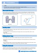
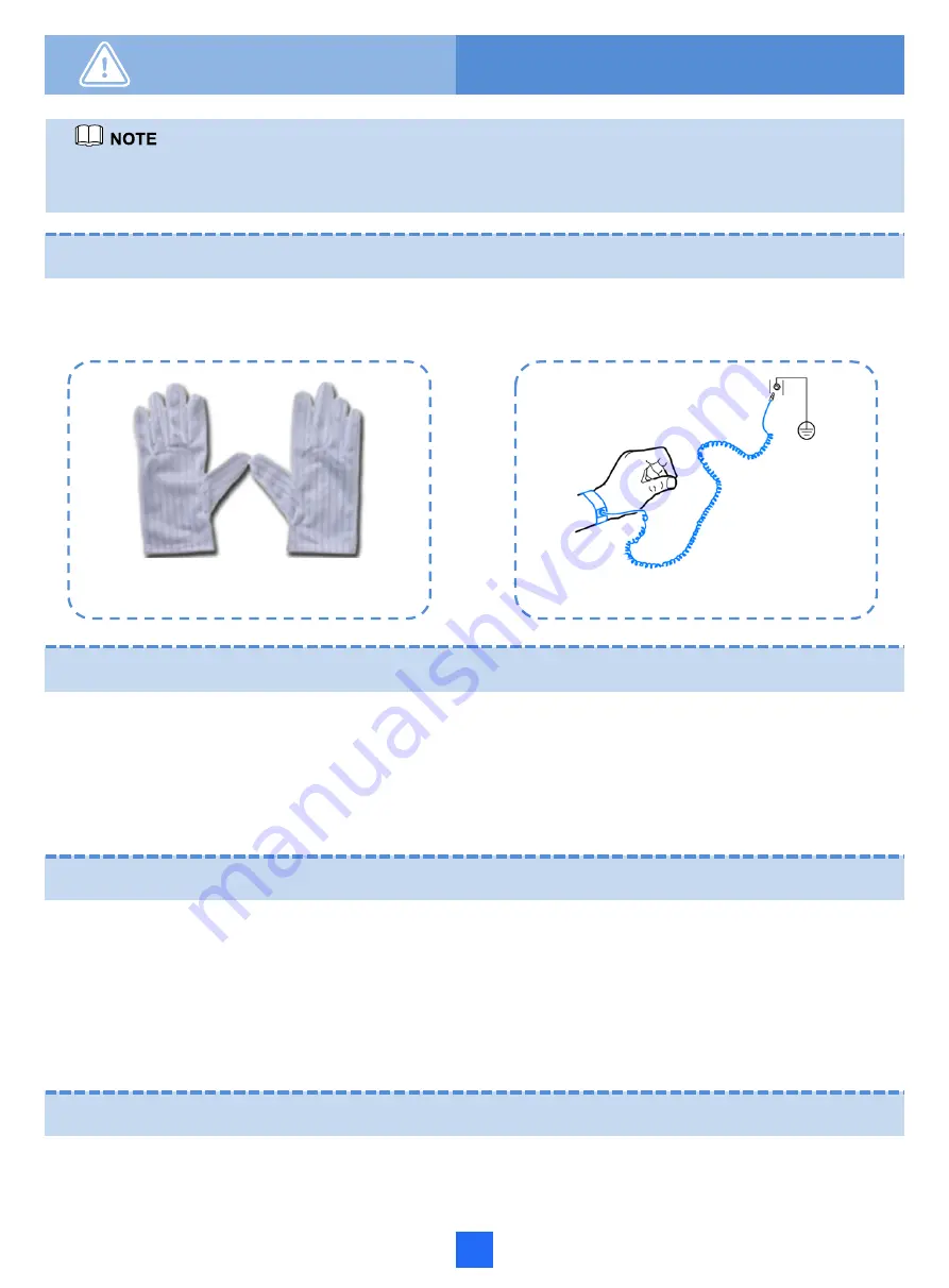
ESD gloves
ESD wrist strap
Affixing labels / tags
Copyright © Huawei Technologies Co., Ltd. 2015 All rights reserved.
•
This document aims to provide simple and distinctive guidelines for hardware installation.
•
This document does not describe operations for the pre-delivery installation of the internal cables and so on. Instead, this
document describers only the operations for on-site installation.
Electrostatic Discharge
Before touching the device, or holding the boards and IC chips, wear the ESD gloves or the ESD wrist strap to
prevent the electrostatic discharge of the human body from damaging the sensitive components. Ensure that the
other end of the ESD wrist strap is properly grounded.
•
The distance between cable ties or binding straps inside the cabinet must be within 250 mm. (For user cable, the
distance must be within 200 mm.)
• Use a diagonal pliers to cut off
the extra part of the cable tie to the end, and ensure that the cable tie is neat
without sharp
edges to prevent hand injury.
Bundling cables
•
After
removing the packing case of the cabinet on the site, take out the desiccant packages from the corresponding paper
bag (Note: Do not tear the own packages of the desiccant). Then, put the desiccant packages at proper places of the cabinet.
After powering on the cabinet, the desiccant packages must be removed and disposed of as an industrial waste.
Using the desiccant
Summary of Contents for F01T500
Page 1: ...HUAWEI TECHNOLOGIES CO LTD F01T500 Quick Installation Guide Issue 07 Date 2017 05 03 ...
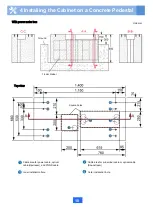
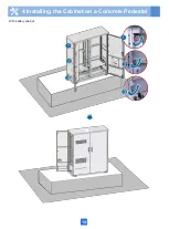
Page 19: ...With battery cabinet 4 Installing the Cabinet on a Concrete Pedestal 14 ...
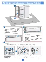
Page 23: ...18 Unit mm 4 Installing the Cabinet on a Concrete Pedestal ...
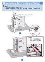
Page 25: ...20 4 Installing the Cabinet on a Concrete Pedestal ...
Page 27: ...22 4 Installing the Cabinet on a Concrete Pedestal ...
Page 38: ...33 With power meter box ...
Page 40: ...35 With power meter box AC power cables AC power cables ...
Page 44: ...39 6 Routing Cables 6 3 Diagram of Cable Connections Between the RPS and MDF RPS Power Supply ...
Page 51: ...46 Route the input Cables of the AC RPR power supply 6 Routing Cables ...
Page 83: ...14 FAQs for Installation 78 ...
Page 84: ...15 FAQs for Installation 79 ...


