61
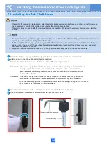
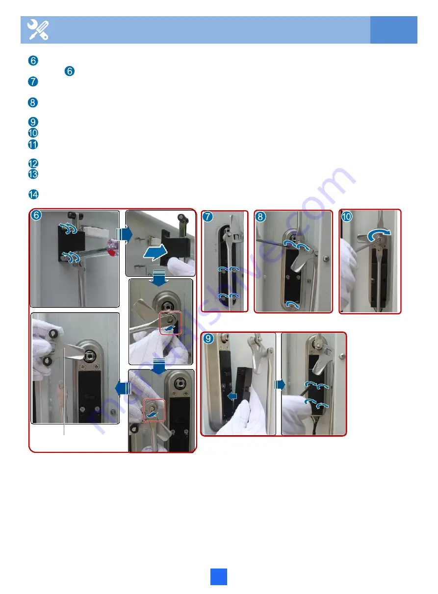
Lock tongue
7 Installing the Electronic Door Lock System
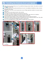
Remove the lock tongue from the lock rod. Then, install the lock tongue removed in step 1 on the lock rod, as shown in
figure in reverse order.
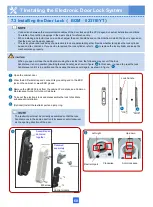
Clear foreign materials on the position where the new door lock is to be installed, and install the door lock on the door
lock position of the cabinet.
Install the cover on the inner side of the cabinet door, and use a Phillips screwdriver to tighten the 3 screws clockwise
on the cover.
Install the control module removed in step1 on the lock body.
Use a Phillips screwdriver to tighten the screws that fix the lock tongue.
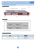
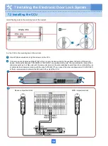
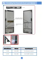
Connect the communication terminal of the door lock to the communication cable of the CCU. For details on
Connections between the 3 compartment door locks and the CCU, see "Table 1".
Verify that the cable of the electric lock does not interfere with the lock rod when the lock rod moves.
(Optional) Use a Phillips screwdriver to loosen the screws that fix the lock core and take out the lock core. Then, install
the new lock core by following the installation procedure in a reverse order.
Use a box-end anti-theft wrench to clockwise fasten the anti-theft screw on the lock handle.
Summary of Contents for F01T500
Page 1: ...HUAWEI TECHNOLOGIES CO LTD F01T500 Quick Installation Guide Issue 07 Date 2017 05 03 ...
Page 19: ...With battery cabinet 4 Installing the Cabinet on a Concrete Pedestal 14 ...
Page 23: ...18 Unit mm 4 Installing the Cabinet on a Concrete Pedestal ...
Page 25: ...20 4 Installing the Cabinet on a Concrete Pedestal ...
Page 27: ...22 4 Installing the Cabinet on a Concrete Pedestal ...
Page 38: ...33 With power meter box ...
Page 40: ...35 With power meter box AC power cables AC power cables ...
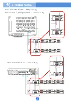
Page 44: ...39 6 Routing Cables 6 3 Diagram of Cable Connections Between the RPS and MDF RPS Power Supply ...
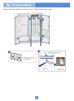
Page 51: ...46 Route the input Cables of the AC RPR power supply 6 Routing Cables ...
Page 83: ...14 FAQs for Installation 78 ...
Page 84: ...15 FAQs for Installation 79 ...

